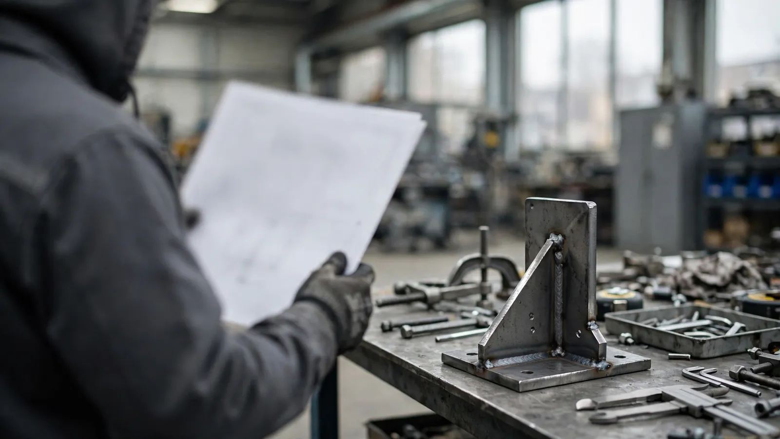
Welding symbols are the shorthand engineers put on a drawing to tell the welder exactly which joint to weld, what type of weld to make, how big it should be, and on which side of the joint it goes. Read each one in a fixed order: arrow, reference line, shape, dimensions, then the tail.
Quick answer: A welding symbol has an arrow pointing at the joint, a horizontal reference line, and an optional tail. A shape drawn below the line applies to the arrow side; above the line, the other side. Size goes to the left of the weld symbol, length and pitch to the right, and process or specification notes go in the tail.
That one rule about the line causes more rework than any other mistake we see on incoming drawings. Below you will find each shape, dimension placement, three worked examples, and where US and international rules disagree.
A welding blueprint can have dozens of joints. Writing “1/4 inch fillet weld, both sides, full length, shop weld, GMAW” beside each would bury the drawing in text. A standard callout carries the same instruction in a few strokes, and any trained welder or inspector reads it the same way.
Think of it as a set of symbols that packs all the information on the weld into one compact mark on engineering and fabrication drawings. The welder needs the location of the weld, the type of weld, its size, and any supplementary information to be used, such as a process or finish.
A good callout carries the welding information and instructions for making the weld, the information needed to complete the joint, without a paragraph of notes. Learning to interpret welding callouts is also the quickest way to understand the types of welds a part needs, whether you buy fabricated parts or plan your own welding projects.
In the United States the rules come from AWS A2.4, Standard Symbols for Welding, Brazing, and Nondestructive Examination, published by the American Welding Society and approved by the American National Standards Institute. Most of the rest of the world uses ISO 2553. China’s national standard, GB/T 324, follows the ISO approach. The two systems share most shapes but differ in a few placements that matter, which we cover below.
One piece of terminology is worth getting right early, because the standard itself is strict about it:
So the triangle for a fillet is one part of the larger callout. Mixing them up rarely causes a bad weld, but it does cause confusing emails.
Every callout is built from the same eight elements, whether it sits on a simple bracket drawing or a full welding blueprint. Only the arrow and reference line are required. Everything else is added when the joint needs it.
The basic weld symbol is a simplified cross-section of the weld. It reflects the geometry of the parts to be joined and the preparation of their edges, which is why a square butt, a bevel and a V each get a different shape. In every case weld metal is deposited into the joint, where filler metal fuses with the base metal to form the joint.
| Element | Where it sits | What it tells you |
|---|---|---|
| Arrow | Connects reference line to the joint | Which joint to weld; defines the arrow side |
| Reference line | Horizontal line, always drawn flat | Carries all other information |
| Basic weld symbol | On, above, or below the reference line | Weld type (fillet, groove, plug, and so on) |
| Dimensions | Left and right of the weld symbol | Size, length, pitch, angle, root opening |
| Supplementary symbols | At the arrow/line junction or on the shape | All-around, field weld, melt-through, contour |
| Finish symbol | Above or below the contour symbol | How the weld face is finished (grinding, machining) |
| Tail | V-shape at the far end of the line | Process, WPS number, or other notes |
| Specification or note | Inside the tail | References that do not fit elsewhere |
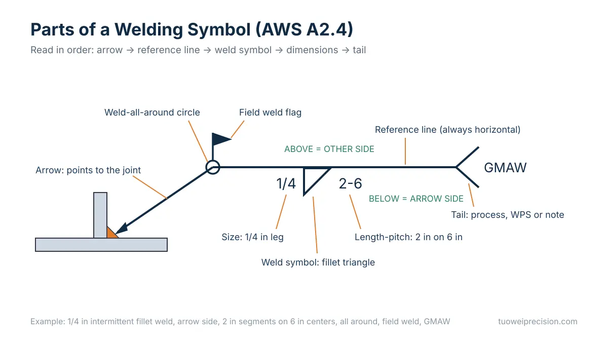
The arrow can attach to either end of the reference line and can bend to reach a crowded joint. Neither changes the meaning. The arrow side is always the side the arrow touches, and the weld symbol distinguishes between the two sides of a joint by which side of the reference line it sits on.
Anything given below the reference line applies to the arrow side. A shape drawn across the center of the reference line has no side at all, which is how spot and seam welds are shown.
The tail of the welding symbol is optional. Information placed in the tail usually names the welding procedure specification (WPS), a process code, or a drawing note. When there is nothing to add, the tail of the symbol is simply left off, and a blank tail of a welding symbol means the shop standard governs.
When the arrow itself has a break in it and points at one specific member, that member is the one to be prepared (beveled or J-cut). This detail matters on bevel and J-groove joints and is easy to miss on a small drawing.
The weld symbol chart below covers every basic symbol defined in the US standard. It is kept as text so you can search, copy, and print it; a PDF version is linked at the end.
| Weld type | Symbol shape | Typical use | Key dimension placement |
|---|---|---|---|
| Fillet | Right triangle, vertical leg on the left | T-joints, lap joints, corner joints | Leg size left; length and pitch right |
| Square groove | Two parallel vertical lines | Thin butt joints, no edge prep | Root opening inside the symbol |
| V-groove | V shape | Butt joints in plate, both edges beveled | Groove angle; depth and weld size left |
| Bevel groove | Single angled line plus vertical line | Butt or T-joint, one edge beveled | Arrow break shows which member is beveled |
| U-groove | U shape | Thick butt joints needing less filler than a V | Groove angle, root radius |
| J-groove | J shape | Thick joints, one member prepared | Arrow break points to prepared member |
| Flare-V groove | Two curved lines facing out | Two rounded parts, such as bars or tube | Weld size in parentheses |
| Flare-bevel groove | One curved line plus vertical line | Round member against a flat plate | Weld size in parentheses |
| Plug | Rectangle | Weld through a round hole in one member | Hole diameter left, filling depth inside |
| Slot | Rectangle (with slot detail) | Weld through an elongated slot | Slot width left; length and pitch defined in a detail |
| Spot | Circle | Resistance or arc spot welds on sheet | Diameter or strength left, number in brackets |
| Seam | Circle with two horizontal lines | Continuous resistance welds | Width left, length right |
| Back or backing | Half circle (filled) | Weld on the back of a groove weld | Placed opposite the groove symbol |
| Surfacing | Two small arcs | Building up a surface | Thickness of buildup left |
| Edge | Two vertical lines bent outward | Edges of thin flanged parts | Size left |
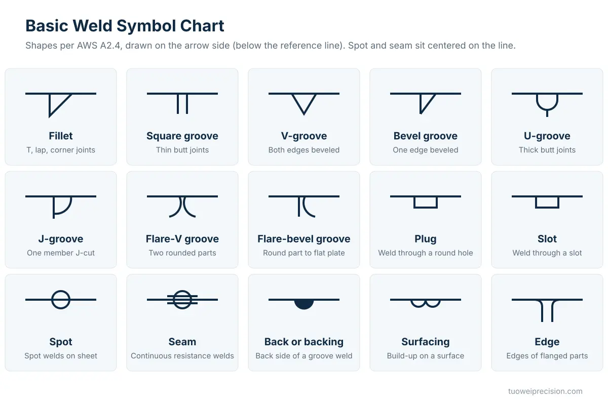
The fillet is the shape you will meet most often. Its triangle always has its vertical leg on the left, no matter which direction the arrow faces. A number to its left, such as 1/4, is the leg size. The leg sets the size of the weld. A number to the right of the fillet weld triangle is the length, and two numbers joined by a hyphen, such as 2-6, mean an intermittent weld of 2-inch segments on 6-inch centers.
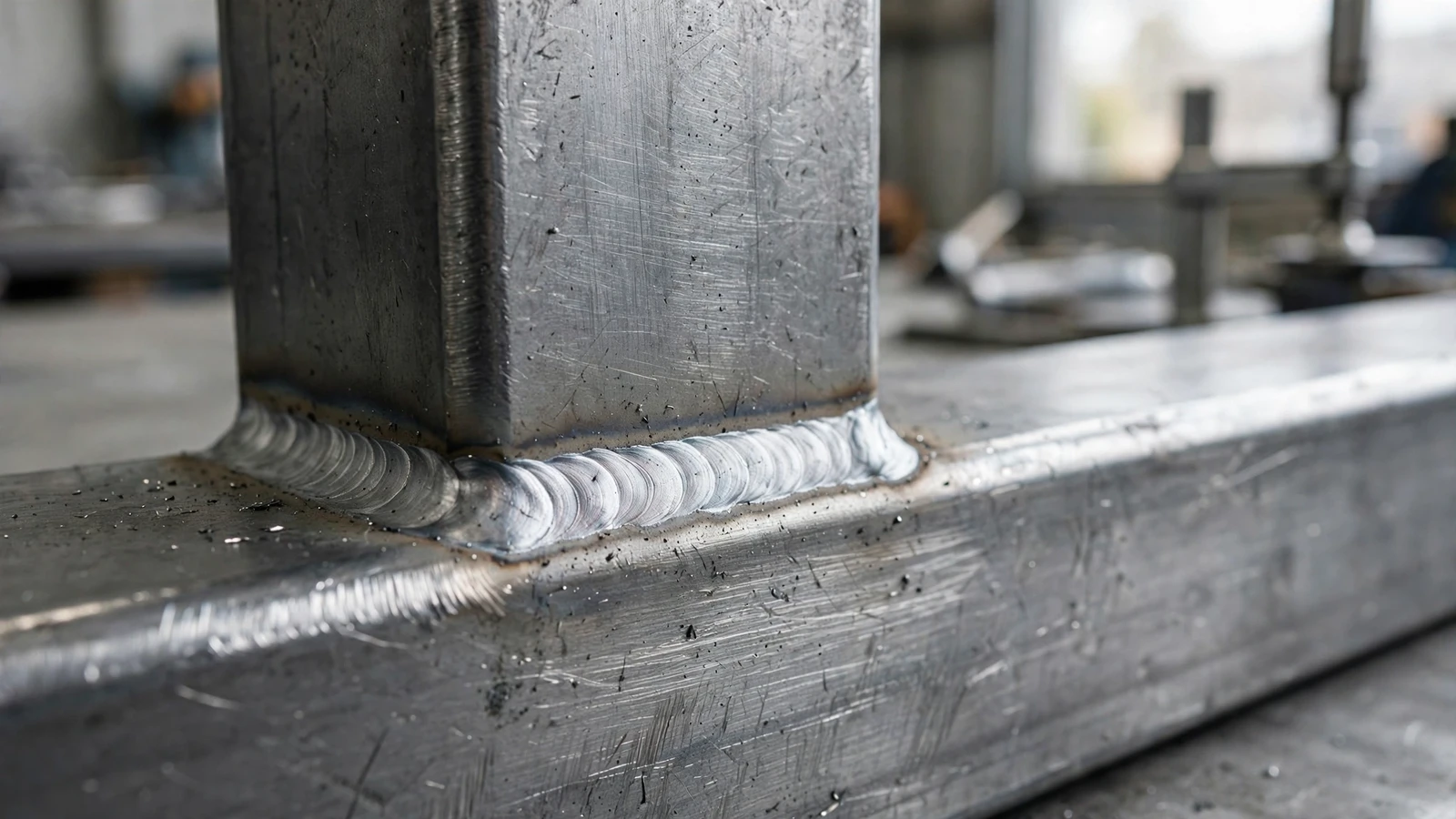
Two triangles, one above and one below the line, mean weld both sides; one triangle means a single weld on one side only. Fillets are the usual choice on lap joints and T joints. If the triangles line up, the segments are chained; if they are offset, the segments are staggered.
A groove weld symbol always describes the edge preparation as well as the weld. The angle written inside or beside the V or bevel is the groove angle. A number in parentheses is the effective weld size, and a number in front of it without parentheses is the depth of bevel. With no size dimensions at all on a single-groove joint, the required weld is complete joint penetration (CJP).
On a plug or slot symbol, a number written inside the rectangle is the depth of filling; no number means fill the hole completely. Spot and seam symbols are centered on the line when there is no arrow side or other side meaning, which is the usual case for resistance welds.
Supplementary symbols add instructions the basic weld symbol cannot carry. They are small and often vanish when a drawing is scaled or scanned.
| Supplementary symbol | Shape | Meaning |
|---|---|---|
| Weld all around | Small circle at the arrow/line junction | Continue the weld around the full joint, such as a tube end |
| Field weld | Small flag at the arrow/line junction | Weld is made on site, not in the shop |
| Melt-through | Filled half circle opposite a groove symbol | Visible root reinforcement from a one-sided weld |
| Consumable insert | Open square opposite a groove symbol | Use a consumable insert of the class named in the tail |
| Backing | Rectangle opposite a groove symbol | A backing strip is used; “R” means remove it after welding |
| Flush or flat contour | Straight line over the weld symbol | Weld face finished flat |
| Convex contour | Outward arc over the weld symbol | Weld face finished convex |
| Concave contour | Inward arc over the weld symbol | Weld face finished concave |
A finish letter placed with the contour symbol states how the contour is reached. Common letters include G for grinding, M for machining, C for chipping, H for hammering, and R for rolling. If the letter is missing, the method is the fabricator’s choice.
The field weld symbol is used for designating welds made on site, and a contour symbol may be used on its own when no finish method matters. Letters used in welding symbols, such as GMAW or GTAW, are used for designating the welding process used in making the weld. Describing the type of weld preparation is left to the basic shape.
Reading a welding blueprint becomes fast once you follow the same order every time. Our inspectors use this sequence when checking customer drawings before quoting.
A triangle below the line, “5/16” to its left, nothing to its right, and “GMAW” in the tail. Read it as: a 5/16-inch fillet weld on the arrow side, running the full length of the joint, made with gas metal arc welding.
Triangles above and below the line, offset from each other. Each has “1/4” on the left and “2-5” on the right. Read it as: 1/4-inch staggered intermittent fillet welds on both sides, 2-inch segments spaced 5 inches center to center. Welders often call this a stitch weld.
A bevel symbol below the line with a break in the arrow, “3/8 (5/16)” to its left and “45°” beside it. A flag sits at the arrow junction. Read it as: bevel the member the arrow points to at 45 degrees, to a depth of 3/8 inch, for an effective weld size of 5/16 inch, welded on the arrow side, in the field rather than the shop.
Most misreads are dimension misreads, not shape misreads. This table shows where each value lives relative to the basic shape.
| Value | Position | Example |
|---|---|---|
| Fillet leg size | Left of the triangle | 1/4 |
| Unequal leg fillet | Left, both legs with “x” | 1/4 x 3/8 (orientation of the weld shown on drawing) |
| Weld length | Right of the symbol | 6 |
| Pitch (intermittent) | Right, after a hyphen | 2-6 |
| Depth of bevel | Left, no parentheses | 3/8 |
| Effective weld size (groove) | Left, in parentheses | (5/16) |
| Groove angle | Inside or next to the groove symbol | 60° |
| Root opening | Inside the groove symbol | 1/8 |
| Plug/slot filling depth | Inside the rectangle | 1/2 |
| Number of spot or projection welds | In parentheses near the symbol | (6) |
| Process or WPS | In the tail | GTAW, WPS-12 |
A missing value does not mean “anything goes.” Usually the shop standard or the referenced WPS controls it. If neither exists, ask before welding.
Most guides skip this, yet it matters to anyone sourcing welded parts internationally. A US drawing read by a shop trained on international rules, or the reverse, can put the weld on the wrong side.
| Topic | AWS A2.4 (United States) | ISO 2553 (international, also basis of GB/T 324) |
|---|---|---|
| Arrow side indication | Weld symbol below the reference line | System A: symbol on the solid line; a dashed line marks the other side |
| Other side indication | Weld symbol above the line | System A: symbol on the dashed identification line |
| Fillet weld size | Leg length | Leg length (z) or throat thickness (a); the letter must be shown |
| Intermittent spacing | Pitch, center to center | Clear gap between segments |
| Units on drawings | Inches common, metric allowed | Millimeters |
Two of these rows cause real defects. First, side placement: ISO 2553 offers a second system that matches the AWS arrangement, so you cannot tell which convention a drawing follows from the symbols alone. Second, size: on an equal-leg fillet the throat is about 0.7 times the leg. A 5 mm weld meant as throat but welded as leg comes out roughly 30 percent undersized.
Our position is simple. State the standard in the title block (“Weld symbols per AWS A2.4” or “per ISO 2553”) on every drawing that leaves your building. It costs one line of text and removes the single biggest source of welding disputes we handle with overseas customers.
These are the problems we see most when engineering drawings arrive for quoting.
Each one usually adds a round of questions before a quote is final, and on tight programs that delay costs more than the weld. Base metal changes what the tail should say as well: a high carbon steel part needs preheat and a qualified WPS, while stainless needs its own filler.
AWS A2.4 does not define a dedicated tack weld symbol. Tack welds are normally left to the welder’s judgment or specified with a note, because they are temporary or are consumed by the final weld. If tack size or spacing matters, write it as a note in the tail or on the drawing.
“Stitch weld” is shop language rather than a separate symbol. It means an intermittent weld, drawn as a fillet weld symbol with a length-pitch dimension such as 2-6.
The number on the left is the size, such as fillet leg length or groove weld size. Numbers to the right give length and, after a hyphen, pitch for intermittent welds. Angles and root openings sit on or inside groove symbols. Process codes like GMAW or a WPS number go in the tail.
A small circle where the arrow meets the reference line is the weld all around symbol. It tells the welder to weld around the entire joint, for example around a tube or a bracket. Without the circle, only the side or segment the arrow touches is welded, so check scanned drawings carefully.
The flag is the field weld symbol. It means the weld is made at the installation site, not in the fabrication shop. Shops leave those joints open, sometimes tack them for shipping, and quote them separately. The flag can point either direction; its direction has no meaning under the US standard, only its presence does.
A weld symbol is only the small shape showing weld type, such as a triangle or a V. The full welding symbol is the complete assembly: arrow, reference line, that shape, dimensions, supplementary marks, and tail. The standard uses the two terms deliberately, and quality documents should follow that wording.
They are welding positions, not symbols. On plate groove welds, 1G is flat, 2G horizontal, 3G vertical and 4G overhead. On pipe, 5G is horizontal and fixed, and 6G is fixed at 45 degrees. An F instead of G, such as 2F, means a fillet weld. Positions appear in WPS and welder qualification records.
Most shapes match, but placement rules differ. AWS puts arrow-side welds below the reference line, while ISO 2553 system A uses a solid and a dashed line. ISO also allows sizing a fillet by throat instead of leg and measures intermittent spacing as the clear gap. Always state which standard a drawing follows.
These callouts only save time when the person reading them sees exactly what the drafter intended. Before you send a welded assembly out for quotes, run through this short checklist:
Our engineering team reviews the weld callouts on every drawing we receive for sheet metal fabrication, and flags anything ambiguous before production starts. If your assembly also needs formed or cut parts, see our precision metal bending service and laser cutting capabilities. For background on how welded parts are produced, read our guides on what sheet metal fabrication involves and how to bend sheet metal.
Ready to check a drawing? Upload it for a free quote or visit Tuowei Precision to see our full range of manufacturing services. Download the free chart PDF below to keep at your workstation.
Download the Welding Symbols Chart (PDF)
Sources and further reading
This guide summarizes common weld callout conventions for reference. Always work to the edition of AWS A2.4 or ISO 2553 named on your drawing and your approved WPS.