焊接符号是工程师使用的简写形式 在图纸上 用于向焊工明确指示应焊接哪个接头、采用何种焊缝、焊缝尺寸应为多少,以及焊缝应位于接头的哪一侧。请按固定顺序逐一阅读:箭头、参考线、形状、尺寸,然后是尾标。
简答: 焊接符号由指向接头的箭头、一条水平基准线以及可选的尾部组成。基准线下方绘制的图形适用于箭头一侧;上方则适用于另一侧。尺寸标注在焊接符号左侧,长度和间距标注在右侧,工艺或规范说明则标注在尾部。
关于线条的那一条规则,所导致的返工比我们在收到的图纸上看到的任何其他错误都要多。下面列出了各种形状、尺寸标注位置、三个示例,以及美国和国际规则存在分歧的地方。
A 焊接图纸 可能包含数十个接头。如果在每个接头旁边都标注“1/4英寸角焊缝,双面,全长,车间焊,GMAW”,图纸上就会布满文字。一个标准的标注只需几笔就能传达相同的指示,而且任何受过培训的焊工或检验员都会以相同的方式理解它。
不妨将其视为一组符号,它将焊缝的所有信息浓缩成工程图和制造图上一个紧凑的标记。焊工需要了解焊缝的位置、焊缝类型、尺寸以及任何需要参考的补充信息,例如工艺或表面处理要求。
一份好的焊标应包含焊接信息和焊接操作说明,以及完成接头所需的信息,而无需冗长的说明文字。无论您是购买加工件还是计划自己的焊接项目,学习解读焊标也是了解零件所需焊缝类型最快捷的方式。
在美国,这些规则来源于 AWS A2.4, 焊接、钎焊和无损检测的标准符号,由美国焊接学会出版,并经美国国家标准协会批准。世界其他地区大多采用 ISO 2553. 中国的国家标准 GB/T 324 遵循 ISO 的方法。这两个系统的大多数形状相同,但在少数几个关键位置上存在差异,我们将在下文中进行说明。
有一个术语值得在早期就弄清楚,因为该标准本身对此有严格规定:
因此,圆角的三角形是较大标注中的一部分。将它们混淆虽然很少会导致焊缝质量问题,但确实会引发令人困惑的邮件往来。
无论是在简单的支架图纸上,还是在完整的焊接蓝图上,每个标注都由相同的八个元素构成。其中,仅箭头和参考线是必需的。其余内容仅在接头需要时才添加。
基本焊接符号是焊缝的简化截面图。它反映了待连接零件的几何形状及其边缘的预备情况,因此方形对接、斜面和V形接头各自具有不同的形状。在任何情况下,焊缝金属都会被堆积到接头处,在那里,填充金属与母材熔合,从而形成接头。
| 元素 | 位置 | 它向你传达了什么 |
|---|---|---|
| 箭头 | 将基准线连接到接头 | 应焊接哪个接头;由箭头方向决定 |
| 基准线 | 水平线,总是画得笔直 | 包含所有其他信息 |
| 基本焊接符号 | 在基准线上、上方或下方 | 焊缝类型(角焊缝、槽焊缝、塞焊缝等) |
| 尺寸 | 焊缝符号的左侧和右侧 | 尺寸、长度、螺距、角度、根部开口 |
| 补充符号 | 在箭头与线的交汇处或形状上 | 全周焊、场焊、熔透焊、轮廓焊 |
| 结束符号 | 等高线符号的上方或下方 | 焊缝表面的处理方式(打磨、机加工) |
| 尾巴 | 线末端的V形 | 工艺、WPS编号或其他备注 |
| 规格或说明 | 尾部内部 | 无法归入其他类别的参考文献 |
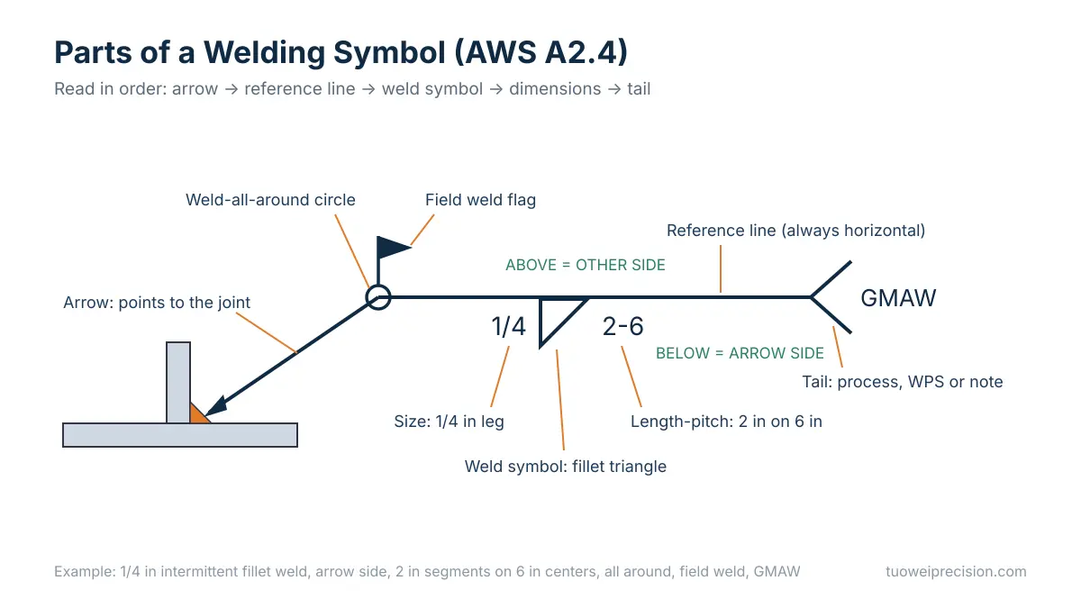
箭头可连接在基准线的任一端,并可弯曲以适应空间狭窄的接头。这两种情况都不改变其含义。箭头侧始终是指箭头接触的一侧,而焊接符号则通过焊接符号位于基准线的哪一侧来区分接头的两侧。
参考线下方标注的任何内容均适用于箭头所指的一侧。画在参考线中心位置的图形则没有侧面,这就是点焊和缝焊的表示方式。
焊接符号的尾部是可选的。尾部通常包含焊接工艺规程(WPS)、工艺代码或图纸注释等信息。如果没有需要补充的内容,则直接省略符号的尾部;若焊接符号的尾部为空白,则表示应遵循车间标准。
当箭头本身带有断口且指向某个特定构件时,该构件就是需要进行预处理(倒角或J型切口)的部位。这一细节在倒角和J型槽接头中至关重要,但在小尺寸图纸上很容易被忽略。
下方的焊接符号表涵盖了美国标准中定义的所有基本符号。该表以纯文本形式呈现,以便您进行搜索、复制和打印;文末提供了PDF版本的链接。
| 焊接类型 | 符号形状 | 典型用途 | 关键尺寸的布置 |
|---|---|---|---|
| 鱼片 | 直角三角形,垂直边在左侧 | T型接头、搭接接头、转角接头 | 左侧为腿部尺寸;右侧为长度和节距 |
| 方槽 | 两条平行的竖线 | 薄对接接头,无需边缘预处理 | 符号内部的根号开口 |
| V型槽 | V形 | 板材的对接接头,两边均作倒角处理 | 开槽角度;深度和焊缝尺寸(左侧) |
| 斜槽 | 一条斜线加一条竖线 | 对接接头或T型接头,一侧倒角 | 箭头断面显示了哪个构件进行了倒角处理 |
| U型槽 | U形 | 厚实的对接接头所需的填充材料比V形接头少 | 槽角、根部半径 |
| J型槽 | J形 | 厚接头,已准备好一个构件 | 箭头断点指向预先定义的成员 |
| 喇叭口-V型槽 | 两条向外延伸的曲线 | 两个圆角部件,例如棒材或管材 | 括号中的焊缝尺寸 |
| 锥形倒角槽 | 一条曲线加一条垂直线 | 圆柱件与平板之间的接触 | 括号中的焊缝尺寸 |
| 插头 | 矩形 | 穿过一个构件上的圆孔进行焊接 | 孔径(左),内部填充深度 |
| 老虎机 | 矩形(带槽口细节) | 穿过长形槽进行焊接 | 槽宽在左侧;长度和间距在详图中定义 |
| Spot | 圆 | 薄板上的电阻焊或电弧点焊 | 剩余直径或强度,括号内为数值 |
| 接缝 | 一个圆,里面有两条水平线 | 连续电阻焊缝 | 宽度在左,长度在右 |
| “Back” 或 “backing” | 半圆(实心) | 在沟槽焊缝背面进行焊接 | 位于凹槽符号的对面 |
| 浮出水面 | 两个小弧 | 构建表面 | 剩余堆积层厚度 |
| Edge | 两条向外弯曲的垂直线 | 薄法兰件的边缘 | 剩余库存 |
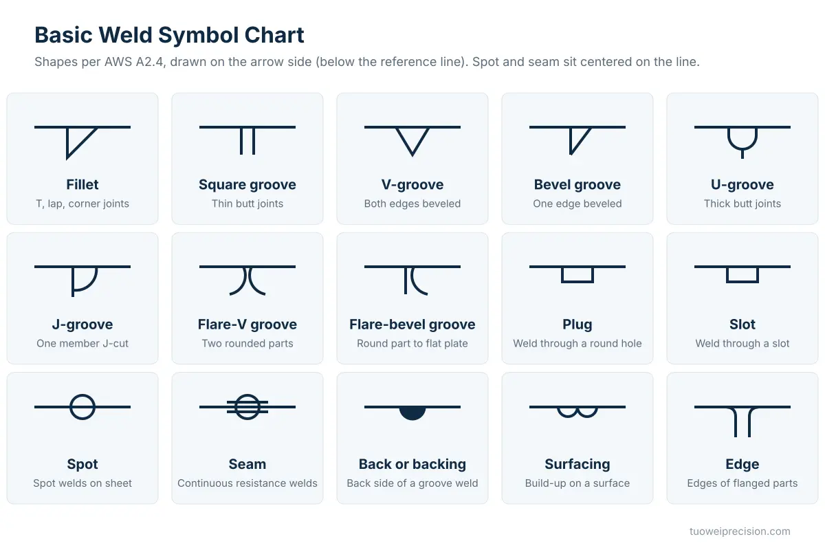
圆角焊缝是最常见的焊缝形状。无论箭头指向哪个方向,其三角形的垂直边始终位于左侧。三角形左侧的数字(例如 1/4)表示该边的尺寸。 竖边决定了焊缝的尺寸。角焊缝三角形右侧的数字表示长度,而由连字符连接的两个数字(例如 2-6)则表示以 6 英寸为间距、每段长度为 2 英寸的间歇焊缝。
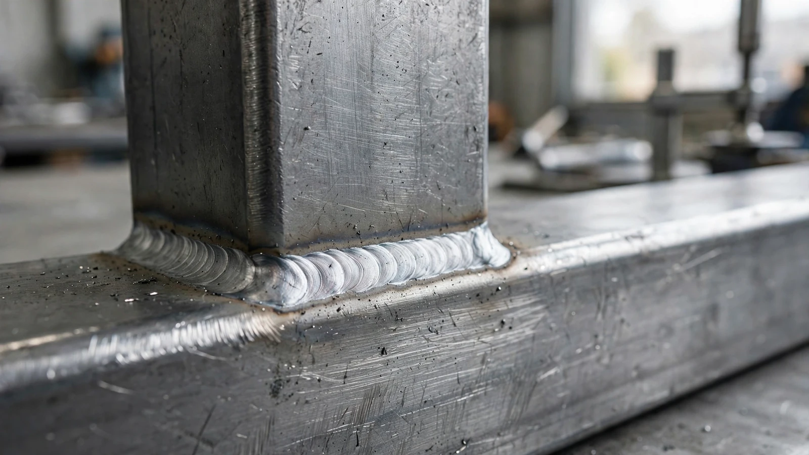
两条三角形符号(一条位于线上方,一条位于线下方)表示两侧均需焊接;一条三角形符号表示仅在一侧进行单道焊接。在搭接接头和T型接头中,通常采用角焊缝。如果三角形符号对齐,则表示段与段是连续的;如果错开,则表示段与段是交错的。
槽焊符号总是同时描述焊缝和焊缝边缘处理。写在“V”字或坡口内部或旁边的角度即为坡口角度。 括号中的数字表示有效焊缝尺寸,其前面的未加括号的数字表示坡口深度。如果单槽接头完全没有尺寸标注,则要求焊缝达到完全熔透(CJP)。
在插接或槽形符号上,矩形内标注的数字表示填充深度;若无数字,则表示完全填满孔洞。当无箭头方向或其他方向含义时,点焊和缝焊符号应居中于线上,这在电阻焊中通常如此。
补充符号用于补充基本焊接符号无法包含的说明。这些符号较小,在图纸缩放或扫描时往往会消失。
| 补充符号 | 形状 | 含义 |
|---|---|---|
| 全周焊接 | 箭头与线条交汇处的小圆圈 | 沿整个接头(例如管端)继续焊接 |
| 现场焊接 | 箭头与线条交汇处的小旗帜 | 焊接是在现场进行的,而不是在车间里进行的 |
| 熔穿 | 与凹槽符号相对的实心半圆 | 单面焊接形成的可见根部加固 |
| 耗材插件 | 与凹槽符号相对的开放方块 | 使用尾部所指类别的耗材插件 |
| 支持 | 与凹槽符号相对的矩形 | 使用背衬条;“R”表示焊接后将其移除 |
| 齐平或平坦的轮廓 | 焊缝符号上方的直线 | Weld face finished flat |
| Convex contour | Outward arc over the weld symbol | Weld face finished convex |
| Concave contour | Inward arc over the weld symbol | Weld face finished concave |
A finish letter placed with the contour symbol states how the contour is reached. Common letters include G for grinding, M for machining, C for chipping, H for hammering, and R for rolling. If the letter is missing, the method is the fabricator’s choice.
The field weld symbol is used for designating welds made on site, and a contour symbol may be used on its own when no finish method matters. Letters used in welding symbols, such as GMAW or GTAW, are used for designating the welding process used in making the weld. Describing the type of weld preparation is left to the basic shape.
Reading a welding blueprint becomes fast once you follow the same order every time. Our inspectors use this sequence when checking customer drawings before quoting.
A triangle below the line, “5/16” to its left, nothing to its right, and “GMAW” in the tail. Read it as: a 5/16-inch fillet weld on the arrow side, running the full length of the joint, made with gas metal arc welding.
Triangles above and below the line, offset from each other. Each has “1/4” on the left and “2-5” on the right. Read it as: 1/4-inch staggered intermittent fillet welds on both sides, 2-inch segments spaced 5 inches center to center. Welders often call this a stitch weld.
A bevel symbol below the line with a break in the arrow, “3/8 (5/16)” to its left and “45°” beside it. A flag sits at the arrow junction. Read it as: bevel the member the arrow points to at 45 degrees, to a depth of 3/8 inch, for an effective weld size of 5/16 inch, welded on the arrow side, in the field rather than the shop.
Most misreads are dimension misreads, not shape misreads. This table shows where each value lives relative to the basic shape.
| 价值 | Position | Example |
|---|---|---|
| Fillet leg size | Left of the triangle | 1/4 |
| Unequal leg fillet | Left, both legs with “x” | 1/4 x 3/8 (orientation of the weld shown on drawing) |
| Weld length | Right of the symbol | 6 |
| Pitch (intermittent) | Right, after a hyphen | 2-6 |
| Depth of bevel | Left, no parentheses | 3/8 |
| Effective weld size (groove) | Left, in parentheses | (5/16) |
| Groove angle | Inside or next to the groove symbol | 60° |
| Root opening | Inside the groove symbol | 1/8 |
| Plug/slot filling depth | Inside the rectangle | 1/2 |
| Number of spot or projection welds | In parentheses near the symbol | (6) |
| Process or WPS | In the tail | GTAW, WPS-12 |
A missing value does not mean “anything goes.” Usually the shop standard or the referenced WPS controls it. If neither exists, ask before welding.
Most guides skip this, yet it matters to anyone sourcing welded parts internationally. A US drawing read by a shop trained on international rules, or the reverse, can put the weld on the wrong side.
| Topic | AWS A2.4 (United States) | ISO 2553 (international, also basis of GB/T 324) |
|---|---|---|
| Arrow side indication | Weld symbol below the reference line | System A: symbol on the solid line; a dashed line marks the other side |
| Other side indication | Weld symbol above the line | System A: symbol on the dashed identification line |
| Fillet weld size | Leg length | Leg length (z) or throat thickness (a); the letter must be shown |
| Intermittent spacing | Pitch, center to center | Clear gap between segments |
| Units on drawings | Inches common, metric allowed | Millimeters |
Two of these rows cause real defects. First, side placement: ISO 2553 offers a second system that matches the AWS arrangement, so you cannot tell which convention a drawing follows from the symbols alone. Second, size: on an equal-leg fillet the throat is about 0.7 times the leg. A 5 mm weld meant as throat but welded as leg comes out roughly 30 percent undersized.
Our position is simple. State the standard in the title block (“Weld symbols per AWS A2.4” or “per ISO 2553”) on every drawing that leaves your building. It costs one line of text and removes the single biggest source of welding disputes we handle with overseas customers.
These are the problems we see most when engineering drawings arrive for quoting.
Each one usually adds a round of questions before a quote is final, and on tight programs that delay costs more than the weld. Base metal changes what the tail should say as well: a high carbon steel part needs preheat and a qualified WPS, while stainless needs its own filler.
AWS A2.4 does not define a dedicated tack weld symbol. Tack welds are normally left to the welder’s judgment or specified with a note, because they are temporary or are consumed by the final weld. If tack size or spacing matters, write it as a note in the tail or on the drawing.
“Stitch weld” is shop language rather than a separate symbol. It means an intermittent weld, drawn as a fillet weld symbol with a length-pitch dimension such as 2-6.
左侧的数字表示尺寸,例如圆角腿长或焊缝沟槽尺寸。右侧的数字表示长度,若为间断焊,则在连字符后标注间距。角度和根部开槽位于沟槽符号上或其内部。工艺代码(如GMAW)或WPS编号则位于符号末尾。
箭头与基准线相交处的一个小圆圈表示“全周焊接”符号。它指示焊工对整个接头进行焊接,例如围绕管材或支架进行焊接。如果没有这个圆圈,则仅焊接箭头所触及的一侧或一段,因此请仔细检查扫描的图纸。
该标记是现场焊接符号。它表示该焊缝是在安装现场完成的,而非在制造车间。制造车间通常会将这些接头留空,有时为便于运输会进行点焊,并单独报价。该标记可指向任意方向;根据美国标准,其方向本身并无特殊含义,仅其存在本身具有意义。
焊接符号仅指表示焊接类型的简图,例如三角形或“V”形。完整的焊接符号则是所有组成部分的总和:箭头、基准线、该简图、尺寸、补充标记以及尾部。该标准有意识地使用了这两个术语,质量文件应遵循这一表述。
这些是焊接位置,而非符号。在板材槽焊中,1G为平焊,2G为横焊,3G为立焊,4G为仰焊。在管道焊接中,5G为横焊且固定,6G为45度角固定。 如果用 F 代替 G(例如 2F),则表示角焊缝。焊接位置会出现在焊接工艺规程(WPS)和焊工资格记录中。
大多数形状一致,但定位规则有所不同。AWS 将箭头侧的焊缝置于基准线下方,而 ISO 2553 A 系统则使用实线和虚线。ISO 还允许根据焊角的喉深而非腿长来确定尺寸,并将间歇间距测量为净间隙。绘图时务必注明遵循哪项标准。
These callouts only save time when the person reading them sees exactly what the drafter intended. Before you send a welded assembly out for quotes, run through this short checklist:
Our engineering team reviews the weld callouts on every drawing we receive for 钣金加工, and flags anything ambiguous before production starts. If your assembly also needs formed or cut parts, see our precision metal bending service 和 laser cutting capabilities. For background on how welded parts are produced, read our guides on what sheet metal fabrication involves 和 如何折弯金属板.
Ready to check a drawing? Upload it for a free quote 或访问 拓维精密 to see our full range of manufacturing services. Download the free chart PDF below to keep at your workstation.
Download the Welding Symbols Chart (PDF)
参考文献与延伸阅读
This guide summarizes common weld callout conventions for reference. Always work to the edition of AWS A2.4 or ISO 2553 named on your drawing and your approved WPS.