
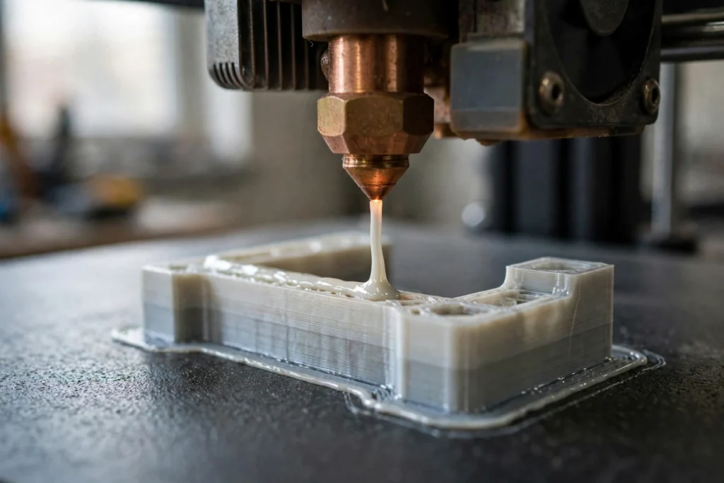
FDM 3D printing is the most widely used way to turn a digital design into a physical plastic part without molds or tooling. It is one of the core methods behind rapid prototyping, because a team can go from a CAD file to a part it can hold, fit, and test in hours or days.
This guide explains what FDM is, how it works, which materials it runs, what accuracy to expect, and how it compares with SLA and SLS. It also covers practical design tips, so you can judge whether FDM suits your part before you commit to a build.
What Is FDM 3D Printing? #
FDM stands for fused deposition modeling. It is an additive manufacturing process: a printer melts thermoplastic filament and pushes it through a heated nozzle, depositing it layer by layer onto a build platform. Each layer cools and bonds to the one below until the part is complete.
Under the ISO/ASTM 52900 standard, FDM belongs to the material extrusion category. It is the opposite of machining, which cuts material away from solid stock. Because FDM only adds material where the design needs it, it handles complex shapes and internal cavities that would be hard or costly to machine.
How FDM Works, Step by Step #
Every FDM build follows the same sequence, from digital model to finished part. The printer software prepares the model, the machine builds it layer by layer, and the part is then cleaned up and checked before use.
- Model: The part is designed in CAD and exported as a mesh file, usually STL or 3MF.
- Slice: Slicing software cuts the model into thin horizontal layers and plans the nozzle path, layer height, infill, and supports.
- Print: The nozzle heats the filament past its melting point and deposits it along the planned path, one layer at a time.
- Support: Overhangs and bridges print on support structures, which are broken away or dissolved after the build.
- Finish: The part is cleaned, supports are removed, and it may be sanded, smoothed, or painted before inspection.
Common FDM Materials #
FDM runs on thermoplastic filament, and the material choice drives strength, heat resistance, and cost. The five materials below cover most everyday FDM work, while engineering grades extend the range further.
| Material | Tensile strength | Heat deflection | Nozzle temperature |
|---|---|---|---|
| PLA | 50–60 MPa | ~55°C | 180–220°C |
| ABS | 34–36 MPa | ~98°C | 235–265°C |
| PETG | 40–50 MPa | ~70°C | 245–260°C |
| Nylon | 50–80 MPa | — | 240–300°C |
| TPU | Varies by grade | — | Varies by grade |
Table sources: tensile strength and heat deflection figures from UltiMaker’s PLA vs ABS vs PETG strength comparison; nozzle ranges from Polymaker’s generic print temperature ranges. Figures are typical published ranges and vary by brand and grade. Nylon heat deflection and TPU figures are omitted because the sources fetched for this article do not publish a single comparable figure — check the filament maker’s datasheet for exact values.
PLA #
PLA is the easiest FDM material to print, with a nozzle range of 180–220°C (Polymaker). Its tensile strength of 50–60 MPa is the highest of these filaments (UltiMaker), it holds detail well, and shrinks 0.3–0.5% as it cools, which keeps warping low. Its weakness is heat: with a heat deflection temperature near 55°C, it suits visual models, fit checks, and indoor parts rather than parts that see heat or load.
ABS #
ABS is a tougher, more heat-resistant general-purpose plastic, widely used for functional prototypes and housings. Its tensile strength of 34–36 MPa is lower than PLA’s, but it absorbs impacts far better, and its heat deflection temperature near 98°C is the highest of the three everyday filaments (UltiMaker). It prints at 235–265°C with a heated bed near 100°C (Polymaker), and warps more as it cools, so it prints best inside an enclosed machine.
PETG #
PETG sits between PLA and ABS. Its tensile strength of 40–50 MPa trails PLA, but it beats PLA on impact resistance, flexibility, chemical resistance, and layer adhesion, and its heat deflection temperature near 70°C is higher than PLA’s (UltiMaker). It prints at 245–260°C (Polymaker), and that balance makes it a good default for parts used outdoors or in damp conditions, such as brackets, mounts, and enclosures.
Nylon #
Nylon is tough, wear-resistant, and flexible enough to absorb impact without cracking, which suits gears, hinges, and clips. Its tensile strength of 50–80 MPa (UltiMaker) is the highest range of the filaments covered here, and it prints at 240–300°C (Polymaker). It absorbs moisture from the air, so filament must be kept dry, and Nylon 12 can shrink up to 2% (Xometry), which makes warping a bigger risk than with PLA.
TPU #
TPU is a flexible thermoplastic polyurethane used for parts that must bend, stretch, or grip, such as seals, gaskets, and protective covers. It prints more slowly than rigid filaments, because the soft filament can buckle in the feed path if pushed too fast.
Engineering-Grade Options #
Beyond the everyday materials, FDM runs carbon-fiber-filled nylons and high-performance polymers. Stratasys lists materials such as Nylon 12CF, which adds chopped carbon fiber for stiffness, ABS CF10, ASA for UV resistance, and ULTEM 9085, a PEI polymer for demanding applications. Polycarbonate, at 60–70 MPa tensile strength (UltiMaker), is another engineering option for strong parts.
Strengths and Limits #
Strengths #
FDM is affordable, fast to set up, and available in a wide material range, which makes it the usual first choice for prototypes, jigs, fixtures, and low-volume parts. Large build volumes suit bigger parts, and the process is clean and office-friendly compared with resin or powder methods.
Limits #
FDM parts show visible layer lines, and fine detail is limited by nozzle width, so it is a poor choice for tiny features or smooth cosmetic surfaces straight off the printer. Parts are also weaker across layers than along them, so print orientation matters whenever a part carries load.
Anisotropy: Why Orientation Matters #
FDM parts are anisotropic: tensile strength in the XY plane is typically 4 to 5 times higher than in the Z direction, so Z tension raises the risk of delamination and fracture (Hubs). That is why load-bearing features should run along the layers, not across them, and why pins or bolts print best horizontally, where shear must cut across solid strands rather than slide layers apart.
Tolerances and Surface Finish #
Xometry lists desktop FDM tolerances at about ±0.5 percent with a lower limit of ±0.5 mm, and industrial FDM at about ±0.15 percent with a lower limit of ±0.2 mm. Layer thickness for FDM is typically 0.05 to 0.3 mm, and the minimum feature size is about 0.2 mm. These are planning values, not guarantees: material, part size, and geometry all shift real results.
Surface finish is the other limit to plan for. As-printed FDM parts show layer steps, especially on curves. Sanding, vapor smoothing, and painting can improve appearance and feel, but each adds time and can change dimensions slightly, so critical fits should be checked after finishing, not before. Xometry notes that support removal can take material with it and shift dimensions, while coatings and paint add a little thickness.
FDM vs SLA vs SLS #
FDM, SLA, and SLS all build parts layer by layer, but they use different materials and suit different jobs. FDM melts filament, SLA cures liquid resin with UV light, and SLS fuses nylon powder with a laser. The table below sums up the practical differences.
| Method | How it works | Typical tolerance* | Best for |
|---|---|---|---|
| FDM | Melted filament, layer by layer | ±0.5% (±0.5 mm) desktop | Strong, large, low-cost parts |
| SLA | UV-cured liquid resin | ±0.5% (±0.2 mm) | Fine detail, smooth surfaces |
| SLS | Laser-fused nylon powder | ±0.3% (±0.3 mm) | Strong parts, no supports needed |
*Tolerance figures are Xometry’s published indicative values and vary with material, size, and geometry. If your part needs tight tolerances, smooth surfaces, or production materials, CNC machining services may be the better route, since machined parts hold far tighter tolerances than printed ones.
Design Tips for FDM Parts #
Good FDM design works with the layer process instead of against it. Small choices at the design stage decide whether a part prints cleanly, holds its fit, and survives in use.
- Orient for strength: Put load-bearing features along the layers, not across them, since bonds between layers are weaker.
- Keep walls even: Even wall thickness cools evenly and warps less than sections that jump between thick and thin.
- Allow fit clearance: Leave extra clearance on mating features, because printed dimensions vary and finishing changes them.
- Support overhangs: Plan supports for overhangs and bridges, and place them where marks will not matter.
- Avoid tiny features: Features below about 0.2 mm may not resolve, so size text, grooves, and thin walls above that limit.
Frequently Asked Questions #
What is the difference between FDM and 3D printing? #
FDM is one type of 3D printing, not a synonym for it. 3D printing is the general term for building parts layer by layer from a digital model, while FDM is a specific method that melts thermoplastic filament and deposits it through a heated nozzle. Other methods include SLA, SLS, and MJF.
What are the downsides of FDM printing? #
The main downsides are visible layer lines, lower detail than resin or powder methods, and weaker strength across layers than along them. Overhangs need support structures, and some materials warp as they cool. Tight tolerances and smooth cosmetic surfaces usually need extra finishing or a different process.
Is FDM the same as PLA? #
No. FDM is the printing process, and PLA is just one material used in it. PLA is a popular, easy-to-print thermoplastic, but FDM printers also run ABS, PETG, nylon, TPU, and engineering plastics. Choosing the material matters as much as choosing the process, because each one behaves differently in use.
What are the typical tolerances for FDM printing? #
Xometry lists desktop FDM at about ±0.5 percent with a lower limit of ±0.5 mm, and industrial FDM at about ±0.15 percent with a lower limit of ±0.2 mm. Real results vary with material, part size, and geometry, so treat these as planning values and confirm critical fits with a test part.
Which is better, SLA or FDM? #
It depends on the part. SLA gives finer detail and smoother surfaces, so it suits small, cosmetic, or highly detailed parts. FDM gives stronger, larger, and usually cheaper parts in engineering thermoplastics. For functional prototypes and parts that must take load, FDM is usually the better choice.


