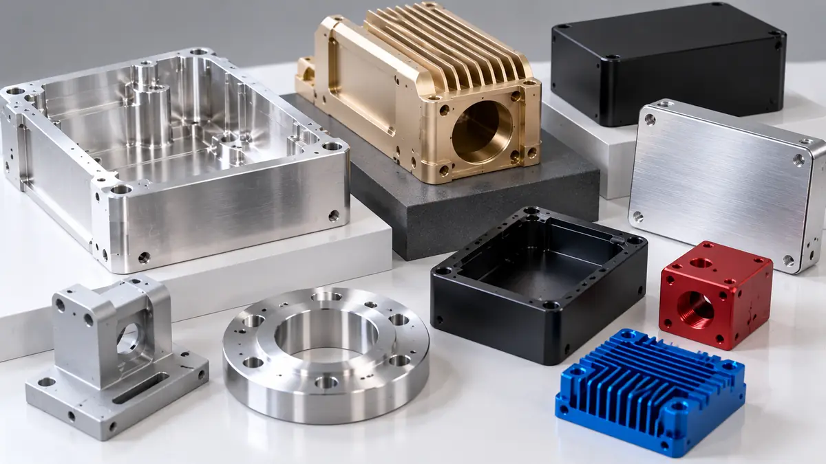
Need expert machining solutions? Our team at Tuowei Proto is here to assist with all your manufacturing needs. Get in touch today for a quote on your ongoing or upcoming projects!
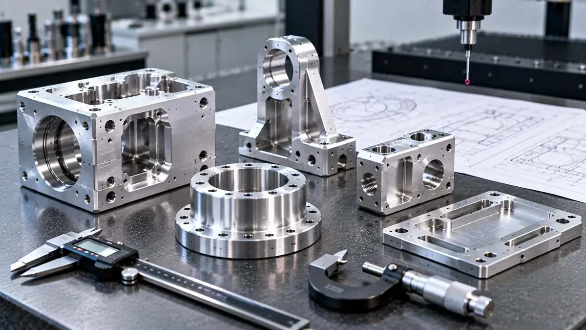
Realistic CNC machining tolerances for aluminum are ±0.005 in (±0.127 mm) for standard features and ±0.001 in (±0.025 mm) for high-precision features on a well-set-up mill. Tighter is possible on turned diameters and reamed holes, but temperature, part size, thin walls, and anodizing decide what you can actually hold and inspect.
Quick answer: Use ±0.005 in as your default and a general tolerance note such as ISO 2768-m for everything else. Apply ±0.001 in only to fits, bores, and sealing faces. Remember that aluminum grows about 23 µm per meter for every 1 °C, and that anodizing adds material to every surface, including bores and threads.
A tolerance is the amount a dimension is allowed to vary from its nominal size. A 20.000 mm hole with ±0.025 mm is acceptable anywhere from 19.975 to 20.025 mm.
Drawings use three kinds:
A tolerance is not the same as a machine’s accuracy, and that difference matters when judging realistic tolerances for aluminum parts. A machine that positions to a few microns still produces parts that vary with tool wear, heat, clamping, and material movement.
These are the aluminum machining tolerances Tuowei publishes for CNC milled parts. They reflect what a production shop can hold repeatably, not a one-off best case.
| Feature type | Realistic tolerance |
| Standard machined features | ±0.005 in (±0.127 mm) |
| High-precision features | ±0.001 in (±0.025 mm) |
| Small components | ±0.002 in (±0.051 mm) |
| Large components | ±0.010 in (±0.254 mm) |
| Threaded features | ±0.005 in (±0.127 mm) |
Turned diameters and reamed or bored holes can usually go tighter than milled features, because the process controls a single axis of size. Long parts and large plates go the other way. The bigger the part, the more heat and internal stress move it.
Our position: if you do not know what tolerance a feature needs, it probably needs the standard one. Tight tolerances belong on features that locate, seal, or carry a bearing.
Different features need different tolerances on aluminum parts. A practical starting point:
| Feature | Common callout | Why |
| Bearing bore | H7 fit | Controls the fit with a standard bearing |
| Dowel pin hole | H7, reamed | Locates mating parts repeatably |
| Clearance hole for a bolt | Loose, general tolerance | Only needs to let the bolt pass |
| Tapped hole | Thread class 6H (metric) or 2B (inch) | Standard thread gauges check it |
| O-ring groove | Tight on depth, looser on width | Depth controls the seal squeeze |
| Cosmetic outer faces | General tolerance | Appearance, not fit, matters |
Most aluminum machining tolerances on a drawing should fall in the loose rows. If more than a handful of features sit in the tight rows, review whether each one really locates, seals, or carries load.
ISO 2768-1 sets general tolerances for linear dimensions that have no individual tolerance on the drawing. You pick a class and write it once, for example “General tolerances ISO 2768-m.”
| Nominal size (mm) | Fine (f) | Medium (m) |
| 0.5 to 3 | ±0.05 | ±0.1 |
| Over 3 to 6 | ±0.05 | ±0.1 |
| Over 6 to 30 | ±0.1 | ±0.2 |
| Over 30 to 120 | ±0.15 | ±0.3 |
| Over 120 to 400 | ±0.2 | ±0.5 |
| Over 400 to 1000 | ±0.3 | ±0.8 |
For most aluminum parts, ISO 2768-m is the right general class for untoleranced aluminum machining tolerances. It is loose enough to machine quickly and tight enough for non-critical features. Use ISO 2768-f only when the whole part needs to be accurate, such as a precision fixture, because it tightens every untoleranced dimension at once.
A general tolerance is not a capability statement. It is a default. Critical features still need their own tolerance.
Aluminum expands roughly twice as much as steel for the same temperature change, at about 23 µm per meter per °C, so temperature eats into aluminum tolerances quickly. That sounds small until you run the numbers:
This is why dimensions are defined at a reference temperature. ISO 1 sets the standard reference temperature for dimensional specification at 20 °C. A part measured warm, straight off the machine, can pass at the mill and fail in a cool inspection room.
In practice, tight-tolerance aluminum parts are allowed to cool to room temperature before final passes and before measurement, and they are checked in a temperature-controlled room.
The alloy and temper change how easily a shop can hold tolerances on aluminum parts, even before the drawing does.
| Alloy and temper | How it behaves | Tolerance tip |
| 6061-T651 | Stress-relieved, stable, cuts cleanly | The safest default for tight features |
| 7075-T651 | Harder, cuts crisply, less smearing | Holds fine features well, costs more |
| 2024-T351 | Machines well, stable | Coat it; corrosion can affect fits over time |
| 5052 | Soft and gummy, burrs heavily | Avoid tight tolerances on machined 5052 |
| MIC6 cast plate | Very flat and stable after machining | Best choice when flatness is the critical tolerance |
If a part has a tight flatness or position callout and the stock is plain T6 or an extrusion, expect movement after roughing. Switching to T651 plate or MIC6 is often cheaper than fighting the distortion with extra operations.
Most problems holding aluminum tolerances come from five sources.
The usual fixes are symmetrical roughing, leaving a finishing allowance, releasing and re-clamping lightly before final passes, and keeping walls as thick as the design allows.
Anodizing converts the aluminum surface into oxide. Part of the coating grows into the metal and part builds outward. The outward part changes your dimensions.
For tolerances on aluminum parts, the effect doubles on features you measure across. A bore shrinks by twice the outward buildup, because both walls grow. External diameters get bigger by the same amount. Threads can tighten enough that a screw will not start.
Hard anodizing (Type III) is much thicker than decorative Type II, so it has a bigger effect on tight features. Three ways to handle the anodizing allowance:
Ask your supplier for their typical coating thickness on the alloy you are using, and build that anodizing allowance into the design. Guessing is how anodized parts stop fitting. Tuowei’s Type II anodizing page describes the standard finish.
Every part can pass inspection and the assembly can still fail. That is tolerance stack-up.
Stack-ups are where individual tolerances for aluminum parts add together. Take three machined spacers stacked in a housing, each 10.00 mm ±0.05 mm.
| Method | Total variation of the stack | When to use it |
| Worst case | ±0.15 mm (0.05 + 0.05 + 0.05) | Safety-critical fits, low volumes |
| Statistical (root sum square) | about ±0.087 mm (0.05 × √3) | High volumes where extremes rarely combine |
If the housing only allows ±0.10 mm, the worst case says the design can fail even though every spacer is in tolerance. The fix is usually not tighter tolerances on every part. It is tightening one part, or adding an adjustment feature such as a shim or a slot.
Run a quick tolerance stack-up on any chain of three or more parts before you release the drawing.
Tight tolerance machining costs more for several reasons at once, and aluminum tolerances are no exception:
The cost does not rise in a straight line. Moving from standard to high precision on one feature is manageable. Moving the whole part to high precision can multiply the price. That is why the cheapest improvement on most drawings is removing tight tolerances that do not do anything.
A tolerance is only real if it can be checked. As a common shop rule of thumb, the measuring tool should be about ten times more precise than the tolerance it checks.
| Tolerance | Typical measuring method |
| ±0.005 in (±0.127 mm) | Calipers, height gauge |
| ±0.001 in (±0.025 mm) | Micrometers, bore gauges, pin gauges |
| Position, flatness, profile | CMM |
| Thread fit | Go/no-go thread gauges |
For a new part, ask for a first article inspection report so the aluminum tolerances on your drawing are verified, not assumed. It should list measured values for every dimension, not just pass or fail. Tuowei outlines its approach on the quality assurance page.
When your incoming inspection disagrees with the supplier’s report, the cause is usually one of three things: a different temperature, a different datum setup, or a different measuring method. Agree on all three before production.
A quote that says “tolerances to ±0.0002 in” tells you what a machine can do on a good day, not what your part will measure. Before placing an order that depends on tight tolerance machining, ask:
A supplier who answers these clearly is more trustworthy than one quoting the tightest number.
A clear drawing gets you realistic quotes and fewer rejections:
A standard tolerance of ±0.005 in (±0.127 mm) is typical for machined aluminum features. Many drawings pair it with a general tolerance note such as ISO 2768-m for untoleranced dimensions. Tighter tolerances are available for critical features but cost more because they need slower cutting and more inspection.
Yes, on suitable features. A well-set-up mill can hold ±0.001 in (±0.025 mm) on bores, fits, and sealing faces. It becomes harder on large parts, thin walls, or after anodizing, because heat, stress, and coating growth move the dimension. Apply it only where the function needs it.
Use ISO 2768-m for most aluminum parts. It suits general features and keeps machining fast. Choose ISO 2768-f only when the entire part must be accurate, such as a precision fixture, because it tightens every untoleranced dimension. Critical features should still carry their own individual tolerances.
Yes. Anodizing adds a coating that partly builds outward, so bores get smaller, outside diameters get larger, and threads can tighten. Hard anodizing has a bigger effect than Type II. Mask critical features, machine to allow for the coating, or state whether dimensions apply before or after anodizing.
Thin walls deflect under cutting forces and spring back after the tool passes, so they measure thicker than programmed. Stress released from the stock and clamping pressure add distortion. Thicker walls, stress-relieved T651 plate, lighter clamping, and symmetrical roughing all help thin features hold tolerance.
Good CNC machining tolerances for aluminum start with a default that is easy to hold, then add precision only where the part needs it. Plan for temperature, stress, and anodizing, check your stack-ups, and agree with your supplier on how each critical feature will be measured.
Tuowei Precision works to these tolerances on its CNC milling, CNC turning, and precision machining lines. Every drawing gets a DFM (design for manufacturing) review before cutting starts. Send your drawing through the Tuowei Precision homepage and our engineers will flag any tolerance that adds cost without adding function.

Written by Andy, Manufacturing Engineer at TUOWEI Precision. Andy specializes in CNC machining, precision manufacturing, and production engineering, with hands-on experience supporting projects from rapid prototyping through full-scale production. He works closely with engineering and manufacturing teams to evaluate materials, tolerances, machining processes, and design manufacturability. His articles provide practical, technically informed insights to help engineers and buyers make better manufacturing decisions, optimize production efficiency, and achieve consistent part quality. Explore TUOWEI Precision’s CNC machining and custom manufacturing solutions for your next project.
From rapid prototypes to scalable production, Tuowei Precision delivers reliable CNC machining with accuracy and consistency at every step. Start your project today.
Keep updated on the real CNC machining, industry trends, and production insights in Tuowei Precision, but is installed to enable you to make better production decisions.