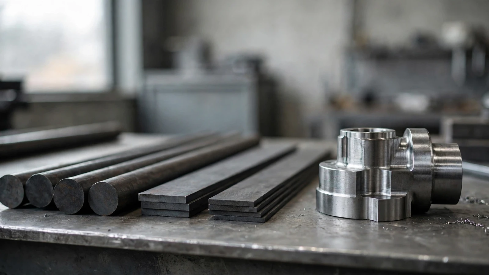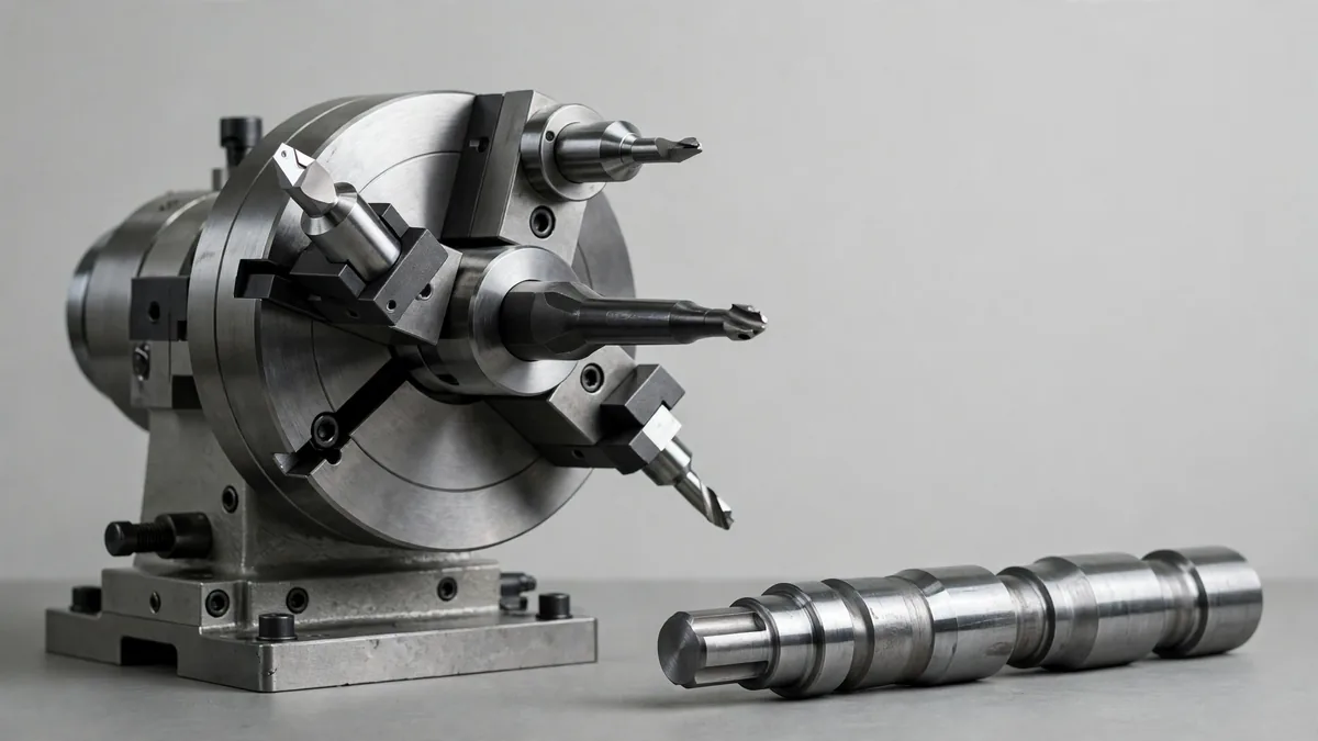
Lathe cutting tools are the single-point and multi-point tools that remove metal from a rotating workpiece. The core set is turning, facing, boring, grooving, parting, threading and drilling tools, plus forming and chamfering tools for special shapes. Most modern turning uses carbide inserts clamped in steel holders rather than ground tool bits.
Quick answer: Pick the tool by the operation first (outside diameter, face, bore, groove, thread or cut-off), then by insert shape and nose radius, then by tool material for the workpiece. A turning tool with an 80° insert and a 0.8 mm nose radius covers most general work on steel and aluminum.
This guide is written from the shop floor. It explains what each tool does, how to read an insert code, which tool material suits which metal, and the setup mistakes that cause chatter, bad finishes and broken inserts.
A lathe spins the workpiece while a stationary tool moves along or across it. That is the opposite of milling, where the tool spins. Because the tool does not rotate, most lathe tools have a single edge, which is why turning tools are often called single-point tools. Drills, reamers and taps used in the tailstock or turret are the exceptions, since they cut with more than one edge.
There are two broad families of metal lathe cutting tools. Ground tool bits are square blanks of high-speed steel (HSS) that the machinist sharpens to the needed shape. Indexable tools hold a replaceable insert in a steel holder. When an edge wears, you rotate the insert to a fresh corner instead of regrinding. On CNC lathes, indexable tooling is the default because it gives repeatable tool positions and faster changeovers. The tool post (or the turret on a CNC lathe), mounted on the carriage’s compound slide, is the component that holds the cutting tools.
It also helps to separate two terms that searches often mix up. A machine tool is the machine itself: the lathe, mill, drill press or grinder. A cutting tool is what the machine holds to remove material. This article covers cutting tools for lathes.
The table below lists the tools you will find on almost every manual or CNC lathe, what each one does, and where it goes on the part.
| Tool | Operation | Typical use |
|---|---|---|
| Turning tool (RH/LH) | Reduces outside diameter | Shafts, pins, general OD work |
| Facing tool | Cuts a flat end face square to the axis | Squaring stock, setting length |
| Boring bar | Enlarges and finishes an existing hole | Accurate internal diameters |
| Grooving tool | Cuts a narrow channel on OD, ID or face | O-ring grooves, snap-ring seats |
| Parting (cut-off) tool | Separates the finished part from bar stock | End of every bar-fed part |
| Threading tool | Cuts external or internal threads | Bolts, fittings, threaded bores |
| Drill | Makes the first hole from the tailstock or turret | Center holes, through holes |
| Center drill | Makes a short, conical start hole | Spotting for drills or live centers |
| Reamer | Finishes a drilled hole to size | Close-tolerance bores |
| Chamfering tool | Breaks sharp edges at an angle | Edge breaks, thread lead-ins |
| Form tool | Cuts a profile in one plunge | Radii, special contours in volume |
| Knurling tool | Presses a diamond or straight pattern | Grip surfaces on handles and knobs |
A note on knurling: a knurling tool forms the surface by pressing it, rather than cutting chips. It sits on the lathe with the cutting tools, but it works on a different principle and needs a rigid setup and plenty of lubricant.
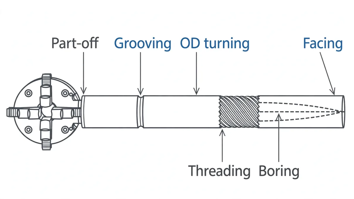
Turning tools come in right-hand and left-hand versions. A right-hand tool cuts while moving toward the headstock, which is the most common direction. Facing usually uses the same holder with an insert that has enough clearance to cut across the end of the part. Use an 80° rhombic or trigon insert when you need strength for roughing, and a sharper 55° or 35° insert when you need to reach into profiles.
A boring bar is a long, slim holder that reaches inside a hole. Its stick-out is the biggest factor in chatter. A useful rule: keep overhang under about four times the bar diameter for steel bars, and switch to carbide or damped bars when you need more reach. Smaller nose radii also reduce chatter in bores.
These tools plunge straight into the part, so they work with a narrow blade that is weak sideways. Set them exactly on center height and square to the axis. Off-center parting tools leave a pip on the part and break blades. Use the shortest blade extension that still reaches the center of the bar.
A threading insert has the thread profile ground on its tip, such as 60° for Unified and metric threads or 55° for Whitworth. The tool moves in a straight line along the part while the lathe synchronizes the feed to spindle rotation. Several light passes build the thread depth. For the common sizes and pitches, see a thread size chart before you set the pitch.
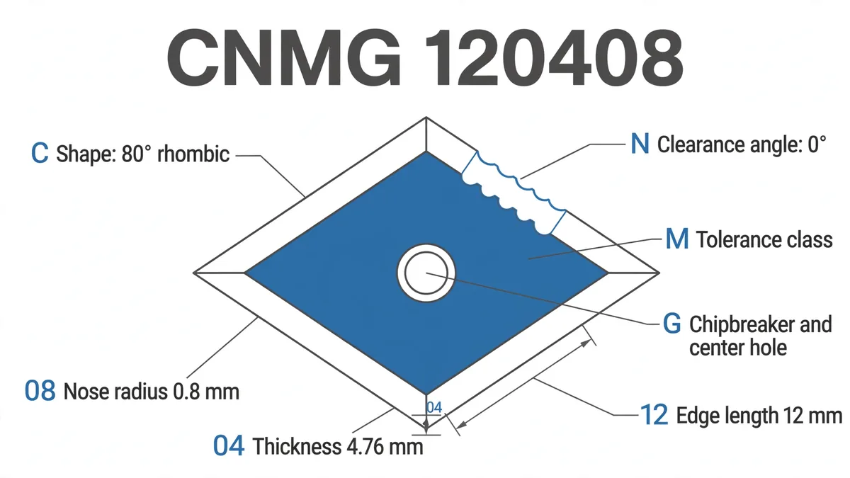
Indexable inserts follow ISO 1832, so the code tells you the shape and size before you open the box. Taking CNMG 120408 as the example:
| Position | Letter or number | Meaning |
|---|---|---|
| 1 | C | Shape: 80° rhombic |
| 2 | N | Clearance angle: 0° (negative insert, used on both sides) |
| 3 | M | Tolerance class |
| 4 | G | Chipbreaker on both faces, with a center hole |
| 5 | 12 | Edge length, about 12 mm |
| 6 | 04 | Thickness, 4.76 mm |
| 7 | 08 | Nose radius, 0.8 mm |
Other common shapes are D (55°), V (35°), T (60° triangle), W (80° trigon), S (90° square) and R (round). Stronger, blunter shapes rough better; sharper shapes profile better. Negative inserts (N) give two-sided use and a stronger edge. Positive inserts (C, P) cut with less force, which suits small parts, boring bars and soft metals.
Cutting tool materials decide how fast you can cut and which metals you can cut at all. These are the ones you will meet on a lathe.
| Tool material | Best for | Watch out for |
|---|---|---|
| High-speed steel (HSS, M2) | Manual lathes, form tools, low speeds, small shops | Softens if overheated; low cutting speed |
| Cobalt HSS (M42) | Tougher steels, interrupted cuts with HSS | Still slower than carbide |
| Uncoated carbide | Aluminum, brass, plastics | Built-up edge in sticky metals |
| Coated carbide (TiN, TiAlN, Al2O3) | Steel, stainless and cast iron, most CNC turning | Brittle in heavy interruptions |
| Cermet | Fine finishing of steel at high speed | Weak in roughing and interrupted cuts |
| Ceramic | Cast iron and heat-resistant alloys at very high speed | Needs very rigid machines |
| CBN | Hardened steel (roughly 45 HRC and above) | Expensive; poor in soft steel |
| PCD (diamond) | Aluminum, copper, composites, plastics | Cannot cut steel (reacts with iron) |
Our default is coated carbide for steel and stainless, polished uncoated or PCD for aluminum, and CBN when we turn hardened parts such as heat-treated D2 tool steel. HSS still earns its place for one-off form tools and on manual machines, where low speeds suit it.
Most guides list angles without saying what they do. Here is what each one changes in practice.
As a starting point for HSS tool bits on mild steel, many shops grind about 8° to 12° back rake and 6° to 8° relief. Treat those as starting values and adjust for the material. With inserts, the geometry is built in, so you choose it through the insert and holder rather than the grinder.
Long, stringy chips wrap around the part and can mark the finish or injure the operator. Chipbreakers in the insert, the right feed and the right depth of cut break chips into short curls. If chips stay long, raise the feed slightly or pick an insert with a tighter chipbreaker for finishing.
These are the problems we see most often, with the usual cause:
Tool life testing is standardized in ISO 3685 if you need to compare grades properly rather than by feel.
On a CNC lathe, the choice of lathe tools also decides cycle time. Fewer tool changes, fewer separate finishing passes and good chip control often save more time than chasing higher cutting speeds. Our CNC turning service plans the tool list this way for every part.
Many searches for lathe tools return woodturning gouges, skews and scrapers. Those are hand-held tools rested on a tool rest, and they cut wood by shearing the fibers. Metal lathe cutting tools are clamped rigidly in a tool post or turret and cut with fixed geometry. The two are not interchangeable, so make sure a tool listing says which type of lathe it is meant for.
The main lathe tools are turning, facing, boring, grooving, parting, threading, chamfering and form tools, plus drills, center drills and reamers used from the tailstock or turret. Knurling tools also sit on lathes, but they press a pattern rather than cut. Most modern lathes use carbide inserts in steel holders.
Ten common cutting tools are turning tools, boring bars, parting tools, grooving tools, threading tools, drills, reamers, taps, end mills and face mills. The first five are typical lathe tools; end mills and face mills belong on milling machines. Each removes material by shearing it away in chips.
The seven basic machine tools usually listed are the lathe, drill press, milling machine, shaper, planer, grinder and power saw. Each holds and moves a cutting tool or workpiece in a different way. Modern CNC lathes and machining centers combine several of these operations in one machine.
Coated carbide is the best general choice for turning steel on CNC lathes because it holds its edge at high cutting speeds. HSS suits low-speed manual work and custom form tools. For hardened steel above roughly 45 HRC, CBN inserts are usually the better option, despite their higher price.
Reduce tool overhang first, then check that the insert is sharp and on center. A smaller nose radius, a sharper positive insert, a lower spindle speed and a rigid workholding setup all help. In bores, use the largest and shortest boring bar that fits, or switch to a carbide or damped bar.
Good turning starts with the right tool for each operation, a sensible insert shape, the correct tool material for the metal, and a rigid, on-center setup. Get those four right and most chatter, poor finish and broken-insert problems disappear.
If you have turned or mill-turned parts to make, our engineers review the drawing, plan the tooling and quote the job. For the process side, see what CNC turning is and how it works, or read how CNC machining works. When you are ready, upload your drawing for a quote or visit Tuowei Precision.
Sources and further reading – International Organization for Standardization, ISO 1832 Indexable inserts for cutting tools: Designation: iso.org – International Organization for Standardization, ISO 3685 Tool-life testing with single-point turning tools: iso.org
Insert grades, cutting speeds and tool angles are typical starting points. Confirm them with your tool supplier’s data for the exact grade and workpiece material.
Angles, nose radii and overhang ratios are typical starting values. Always follow the insert manufacturer’s cutting data for your grade and machine.