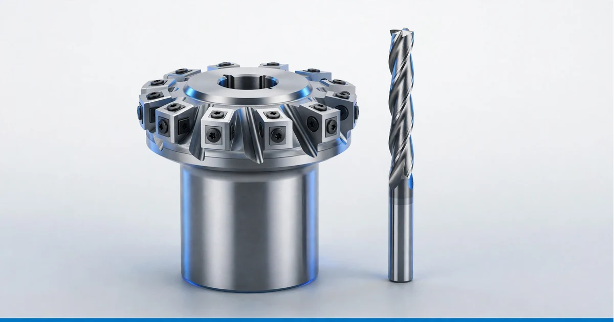
Face milling and peripheral milling are the two basic ways a milling cutter can remove material from a workpiece. The difference comes down to which part of the cutter does the work. In face milling, the cutter axis is perpendicular to the surface being machined and the cutting happens at the end face of the tool. In peripheral milling, the cutter axis is parallel to the machined surface and the teeth on the outside diameter (the periphery) do the cutting.
That single difference in orientation changes the cutting forces, the surface finish, the tools you use and the features you can make. This peripheral milling guide explains both methods in plain terms, corrects a few common myths, and gives you the numbers machinists actually use: stepover, lead angle, chip thinning and a worked feeds and speeds example.

| Factor | Face milling | Peripheral milling |
|---|---|---|
| Cutter axis vs machined surface | Perpendicular | Parallel |
| Teeth doing the cutting | End face (with corner edges) | Outside diameter (flutes) |
| Typical surface produced | Large flat faces, top surfaces | Walls, shoulders, slots, profiles, contours |
| Main force direction | Axial, into the spindle | Radial, pushing the tool sideways |
| Typical tools | Face mills, shell mills, fly cutters, high feed mills | End mills, slab mills, side and face cutters, slitting saws |
| Typical width of cut | 60% to 80% of cutter diameter | 5% to 100% of tool diameter |
| Typical depth of cut | Shallow axial depth, often 0.5 to 5 mm | Deep axial depth possible, often 1 to 3 times diameter on walls |
| Main risk | Poor flatness on thin plates, step lines between passes | Tool deflection, wall taper, chatter on long tools |
| Best finish on | Flat faces (Ra 0.4 to 1.6 µm with wiper inserts) | Side walls (Ra 0.8 to 3.2 µm in a finish pass) |
| Machine | Vertical machining center (most common) | Vertical or horizontal machine |
In short, the difference between face milling and peripheral milling depends on which teeth on the cutter do the work. Face milling produces flat faces with the cutter face, while peripheral milling and face milling together cover almost every prismatic part. Common peripheral milling applications are walls, slots, pockets and profiles, so peripheral milling is preferred wherever the workpiece needs a side feature. In a real CNC milling process, milling often combines both: peripheral milling is one of the two basic milling applications, and the right milling strategy depends on part geometry, tool engagement and material, from aluminum to stainless steel. Choosing milling tools is part of that strategy, because every milling cutter to remove material is built for one of these two cutting directions.
Face milling is a machining process in which the milling cutter is positioned perpendicular to the workpiece, so the cutter face and the bottom face of the tool remove material to produce a flat surface. A face mill is usually a large diameter body (50 to 160 mm is common on CNC machining centers) with several indexable carbide inserts around its rim. Most of the metal is cut by the insert corners and the short edge near the bottom of the tool, while the flat bottom edge (or a wiper flat on the insert) smooths the surface.
Shops use face milling to:
The lead angle (also called entering angle) is the angle between the cutting edge and the surface. It controls chip thickness, force direction and what shapes the cutter can make:
Peripheral milling (also called plain milling) is a machining process that removes material from the workpiece with the teeth on the circumference of the cutter, while the cutter axis stays parallel to the machined surface. On a modern vertical machining center, this is what an end mill does when it cuts the side wall of a pocket or the outside profile of a part. On a horizontal mill, an arbor mounted slab mill does the same thing to a wide flat surface.
As a machining operation, peripheral milling is used for anything that is not a top face: walls, shoulders, slots, keyways, outside profiles and 3D contours. Because the flute length can be long, it can cut deep features in one pass that a face mill cannot reach.
A typical peripheral milling operation on a CNC machining center runs in five steps:
Peripheral milling tools on vertical machining centers include solid carbide end mills (2 to 6 flutes), indexable shoulder mills and chamfer mills. Peripheral end milling is the most common form today. On horizontal mills, slab mills, side and face cutters, slitting saws and form cutters are mounted on an arbor. Long walls and deep slots favor short, large diameter tools, because rigidity sets the limit before spindle power does.
| Advantages | Limitations |
|---|---|
| Cuts deep walls, slots and profiles that a face mill cannot reach | Side load bends the tool, so walls can taper |
| One end mill can rough and finish many features in one setup | Long tools chatter, which limits depth and finish |
| Light stepover toolpaths give high feed and long tool life | Scallop lines on floors if used for flat areas |
| Good wall finish and position accuracy with a spring pass | Internal corners always keep the tool radius |
| Operation | What it makes | Typical tool |
|---|---|---|
| Slab (plain) milling | Wide flat surface parallel to the cutter axis | Helical slab mill on a horizontal arbor |
| Side milling | Vertical face on one side of the part | Side and face cutter, end mill |
| Straddle milling | Two parallel faces at once, for example the width of a lug | Two side cutters on one arbor |
| Gang milling | Several surfaces in one pass in production | Multiple cutters on one arbor |
| Slot milling | Slots and keyways, often full width cut | End mill, slot drill, slitting saw |
| Profile milling | Outside and inside 2D contours | End mill |
| Shoulder milling | Floor plus wall at 90° (combined face and peripheral) | Square shoulder mill, end mill |
| Form milling | Special profiles such as radii or gear teeth | Form cutter |
In face milling the force runs mostly along the spindle axis, so the machine’s stiffest direction takes the load. In peripheral milling the force pushes the tool sideways. That sideways force bends the tool, which is why peripheral milling is far more sensitive to tool stickout and diameter. A useful rule: tool deflection rises with the cube of stickout, so doubling stickout gives about eight times the bend.
Several popular guides say face milling uses the full width of the cutter. In practice, running a face mill dead center on a surface the same width as the cutter is one of the worst setups: chips are thinnest at entry, edges rub, and vibration rises. The standard practice is to choose a cutter about 20% to 50% wider than the cut and offset it so the width of cut is about 60% to 80% of the cutter diameter. For faces wider than the cutter, plan overlapping passes with about 10% to 20% overlap.
Peripheral milling uses a much wider range of radial engagement, from a 5% finishing pass to a 100% slot.
The actual chip thickness is not the same as the programmed feed per tooth (fz). Two things thin the chip:
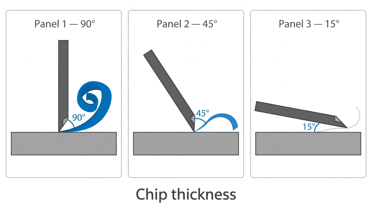
Lead angle (face milling): h_ex = fz × sin(κr). A 45° face mill at 0.20 mm/tooth makes a chip only about 0.14 mm thick. To get the chip load the insert is designed for, you raise the feed by about 1.4×. A 15° high feed cutter thins the chip to about 26% of fz, which is why those tools run at 1 to 2 mm/tooth.
Radial engagement (peripheral milling): when width of cut (ae) is under half the tool diameter (D), h_ex = fz × 2√((ae/D) × (1 − ae/D)). At 10% radial engagement the chip is only 0.6 × fz. If you do not compensate, the tool rubs instead of cutting, heats up and wears fast. This is the reason modern high efficiency and trochoidal toolpaths use light stepovers with high feed rates.
Face milling gives the best result on flat surfaces. A finishing pass with wiper inserts can reach Ra 0.4 to 0.8 µm on aluminum and Ra 0.8 to 1.6 µm on steel. The typical pattern is a crosshatch of arcs. If the spindle is not perfectly square to the table (tram), the trailing edge recuts the surface and leaves a crosshatch. A slight tilt so that only the leading edge cuts gives a cleaner one direction pattern.
Peripheral milling gives the best result on walls. A light finish pass (about 0.1 to 0.5 mm radial) with a sharp end mill in climb milling typically gives Ra 0.8 to 3.2 µm. Where peripheral milling is used on a floor (for example, a slab mill or a stepover pattern with an end mill), it leaves scallop lines that are harder to remove than face milling marks.
It is a myth that face milling always removes metal faster. A large face mill with many inserts removes a lot of material per minute on open flat areas, but an end mill using its full flute length on a wall with a light stepover can match or beat it, especially on modern high speed machines. The worked example below shows the actual numbers.
Face milling controls flatness and parallelism of a face. Peripheral milling controls wall position, perpendicularity and profile. On a well maintained machine, ±0.025 mm on wall position and 0.02 to 0.05 mm flatness over 100 mm are realistic. Tighter results need a finish pass, stable workholding and stress relieved stock. See our guide on realistic CNC machining tolerances for more detail.
The key peripheral milling parameters and face milling parameters use the same formulas:
Where Vc is cutting speed (m/min), D is tool diameter (mm), z is the number of teeth, ap is axial depth and ae is radial width of cut.
Face milling 6061 aluminum, 63 mm face mill, 5 inserts, 90° lead
Peripheral milling a wall in 6061, 12 mm 3 flute carbide end mill
The face mill wins on an open flat area, but the end mill does work the face mill cannot do at all: a 24 mm deep wall in one pass. Values like these are starting points. Always check the tool maker’s data for your exact grade, coating and machine.
Typical starting values for a 10 to 12 mm carbide end mill in a side milling cut. Check your tool maker’s data before running.
| Material | Cutting speed Vc (m/min) | Feed per tooth fz (mm) | Notes |
|---|---|---|---|
| Aluminum 6061 / 7075 | 300 to 600 | 0.05 to 0.15 | Polished 2 or 3 flute, air or mist to clear chips |
| Mild steel 1018 / 1045 | 120 to 200 | 0.04 to 0.10 | AlTiN coated 4 flute, flood coolant |
| Stainless 304 / 316 | 70 to 120 | 0.03 to 0.08 | Never let the tool rub, it work hardens the wall |
| Gray cast iron | 100 to 180 | 0.05 to 0.12 | Often cut dry with air, watch for edge chipping at exit |
| Titanium Ti-6Al-4V | 40 to 70 | 0.03 to 0.07 | Low radial engagement, high pressure coolant |
| Nickel alloys (Inconel 718) | 20 to 40 | 0.02 to 0.06 | Very low radial engagement, sharp coated tool, rigid setup |
| Brass C360 | 150 to 300 | 0.05 to 0.15 | Uncoated or DLC, can run dry |
| Acetal (POM) and other plastics | 150 to 300 | 0.08 to 0.20 | Sharp 1 or 2 flute, air blast to stop melting |
Peripheral milling has one extra choice that face milling mostly avoids: the direction the cutter rotates relative to the feed.

| Climb milling (down milling) | Conventional milling (up milling) | |
|---|---|---|
| Chip shape | Thick to thin | Thin to thick |
| Tool life | Longer, less rubbing | Shorter, edge rubs at entry |
| Surface finish | Better | Worse, more work hardening |
| Best for | CNC machines with ballscrews, finishing, stainless and titanium | Old manual machines with backlash, hard scale or cast skin |
On CNC machining centers, climb milling is the default for almost all peripheral cuts. In face milling, both happen at once across the cutter, which is another reason to offset the face mill so more of the cut is in the climb direction.
This is the question buyers and designers really ask. Use this map when you review a part:

| Feature on the drawing | Usual operation | Why |
|---|---|---|
| Top face, datum face, sealing face | Face milling | Best flatness and finish on large flats |
| Outside profile, side walls | Peripheral milling (end mill) | Cutter axis parallel to the wall |
| Pocket walls | Peripheral milling | Same as above, finished with a light radial pass |
| Pocket floor | End mill bottom (a small face milling action) | Face mill cannot fit inside the pocket |
| Step or shoulder at 90° | Shoulder milling (both at once) | Square shoulder cutter or end mill cuts floor and wall together |
| Slots and keyways | Peripheral slot milling | Full width cut, watch chip evacuation |
| 45° chamfer on edges | Chamfer mill (peripheral) | Edge of the tool forms the angle |
| Large wide flat on a long part | Face milling, or slab milling on a horizontal machine | High removal rate |
| 3D surface, mold cavity | Ball end mill contouring | Peripheral and tip cutting combined |
| Problem | Usually in | Likely cause | Fix |
|---|---|---|---|
| Wall taper (wider at bottom) | Peripheral | Tool deflection from long stickout or heavy radial cut | Shorter tool, larger diameter, light spring pass, variable helix end mill |
| Chatter marks | Both | Low rigidity, wrong engagement, long overhang | Change rpm by 10% to 15%, reduce stickout, use variable pitch tool |
| Step lines between passes | Face | Spindle tram out, insert height runout | Tram the head, use wiper inserts, overlap passes 10% to 20% |
| Plate warps after unclamping | Face | Residual stress in the stock | Machine both sides alternately, rough, release clamps, then finish |
| Burrs on exit edge | Both | Feed direction off the edge, sharp lead angle | Use 45° cutter, chamfer pass, plan exit into material |
| Fast edge wear in stainless | Peripheral | Rubbing from radial chip thinning | Increase fz to compensate, climb mill, coolant through tool |
Knowing which operation makes each feature helps you design cheaper parts:
If your part needs both tight flatness and deep pockets, 5-axis milling can reduce setups. Read when 5 axis machining is worth the cost.
At Tuowei Precision, parts are process planned before cutting starts. Large datum and sealing faces are face milled first with indexable cutters to create a stable reference. Walls, pockets, profiles and slots are then rough machined with high-efficiency milling toolpaths and finished with a separate light radial pass to hold position and finish. Aluminum, steel, stainless and titanium each get their own cutting data and tool coatings.
Need parts that combine flat datum faces, deep pockets and tight wall tolerances? Explore our CNC milling services or upload your drawing for an instant quote.
Not exactly. End milling is a tool category, not a cutting direction. An end mill does peripheral milling when its side flutes cut a wall, and it does a small amount of face milling when its bottom edges cut a floor. Most CNC end mill work is a mix of both.
Face milling gives the better finish on flat faces, especially with wiper inserts. Peripheral milling gives the better finish on side walls. Each method is best on the surface it is designed to cut.
Only a 90° (square shoulder) face mill can. A 45° or high feed face mill leaves an angled or radiused step because of its lead angle.
Yes. In slot milling the tool cuts with its full diameter in the side flutes. It is one of the hardest peripheral cuts because chips have nowhere to escape, so feeds are lower than in side milling.
Use about 60% to 80% of the cutter diameter as the width of cut, with the cutter offset from the center line. For surfaces wider than the cutter, overlap passes by about 10% to 20%.
Slab milling is peripheral milling with a wide cylindrical cutter on a horizontal arbor. It cuts a flat surface with the teeth on its outside. Face milling cuts the same kind of flat surface with the end of a cutter held perpendicular to it. Face milling is far more common on CNC machining centers today.
The side load bends the tool away from the wall, more at the tip than at the shank. The result is a wall that is thicker at the bottom. Shorter tools, lighter finish passes and a spring pass fix it.
Most peripheral milling today is done on CNC vertical machining centers with end mills. Horizontal milling machines with arbor mounted slab, side and straddle cutters are still used for wide surfaces and high volume production.
Side milling is a type of peripheral milling that cuts a vertical face with the teeth on the side of the cutter. End milling is a broader term for any cut made with an end mill, which can use its side teeth, its end teeth or both at once.
Milling is usually more complex to program and set up, because the tool moves in several axes around a fixed part. Turning is simpler for round parts, since the part spins and a single point tool shapes it. See our guide to lathe cutting tools for the turning side.