Need expert machining solutions? Our team at Tuowei Proto is here to assist with all your manufacturing needs. Get in touch today for a quote on your ongoing or upcoming projects!
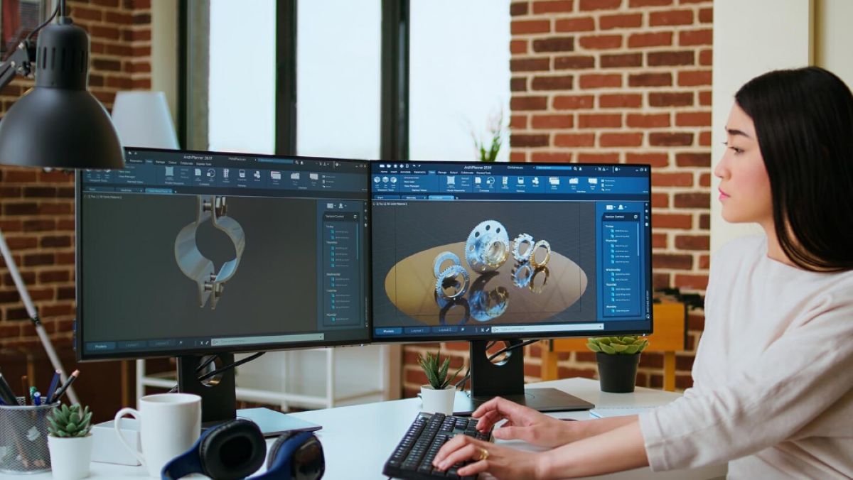
A model that looks finished in CAD is not automatically a model a shop can quote. Every week machinists open files with no tolerances attached, meshes exported instead of solids, corner radii smaller than any cutter that exists, and features positioned where no tool can reach. Each one costs a day in emails before anything is cut.
This guide covers what happens to your file after it leaves your screen. It compares Onshape and Fusion 360 specifically for work that ends up on a 5-axis machine, explains which file formats carry the data a shop needs, and lists the modeling decisions that quietly determine whether a part is straightforward or expensive to machine.
Four things, in order of how often they are missing. A watertight solid model in a neutral format such as STEP or Parasolid, so the geometry can be read into CAM without repair. Tolerances, either attached to the model or supplied on a dimensioned drawing, since a model on its own carries no accuracy requirement. A material specification, including alloy and condition. And a statement of which surfaces are functional, because a shop that does not know which dimensions matter will protect all of them, which costs time and money.
Everything else is a refinement on those four. A part that arrives with all four can usually be quoted the same day.
Both are capable parametric modelers and both are used successfully by teams whose parts end up on 5-axis machines. The meaningful difference for machining is not modeling power. It is whether manufacturing lives inside the same environment as the design.
| Consideration | Onshape | Fusion 360 |
| Core strength | Cloud native CAD with built in version control and branching | Integrated CAD, CAM and simulation in one environment |
| Where it runs | Entirely in the browser, no local install required | Desktop application with cloud data management |
| Manufacturing capability | No native CAM; relies on partner applications or export to a separate CAM system | CAM is built in, with toolpath generation alongside the model |
| 5-axis approach | Handled by whichever CAM system the model is exported to | Positional 3+2 in the base product, with simultaneous multi axis requiring an extension |
| Collaboration | Strong, since every user works on the same live document | Good, through shared cloud projects |
| Revision control | Built into the platform with named versions and branches | Version history within the cloud project |
| Typical user | Distributed teams and organizations that value browser access and design history | Teams who want design and manufacturing in one seat |
If your parts are machined by an outside supplier, the CAM difference barely affects you. You model the part, export a neutral file, and the shop programs it in whatever system they run. Onshape and Fusion 360 are equally viable in that workflow, and the choice comes down to how your team prefers to work rather than to machining capability.
If you machine parts in house, the difference becomes significant. Fusion 360 keeps toolpaths associative to the model, so a geometry change updates the program instead of requiring a reprogram. Onshape has no native CAM, so an in house workflow means either a partner application or an export into a separate CAM package, which introduces a file handoff every time the design changes.
There is a middle case worth naming. Teams that model in Onshape and outsource machining often get the best of both, because they keep the collaboration and version control benefits while the supplier absorbs the CAM work entirely. That is a perfectly sound arrangement and it is more common than software comparisons suggest.
| Format | What it carries | Use for machining |
| STEP (.step, .stp) | Exact solid geometry, and PMI data in the AP242 flavor | The default choice, accepted by every shop |
| Parasolid (.x_t) | Exact solid geometry in a widely used modeling kernel format | Excellent where the shop’s CAM uses the same kernel |
| IGES (.igs) | Surface geometry, often without a stitched solid | Acceptable but dated; surfaces can arrive unstitched and need repair |
| Native files (.f3d, Onshape document) | Full feature history and design intent | Useful as a supplement, but not every shop can open them |
| STL (.stl) | A triangulated mesh approximation of the surface | Not suitable for machining; see below |
| 3MF (.3mf) | Mesh with additional metadata | Additive manufacturing, not machining |
| 2D drawing (PDF or DWG) | Dimensions, tolerances, datums, finish and material notes | Still needed alongside the model unless tolerances are embedded |
An STL file is a mesh of flat triangles approximating the real surface. A cylinder becomes a many sided polygon, and a smooth curve becomes a series of facets. That approximation is invisible on a printed part and unacceptable on a machined one, because the CAM system will faithfully cut the faceted approximation rather than the true surface.
STL files still arrive at machine shops regularly, usually from teams whose habits come from 3D printing. If a shop asks for a solid model after you sent an STL, that is why. Send STEP or Parasolid instead, and keep STL for additive work where it belongs.
A solid model describes shape. It does not describe how accurately that shape must be achieved. A hole modeled at 10 mm carries no information about whether it must be held within a few hundredths or whether a general tolerance is acceptable, and those two requirements produce very different prices.
There are two ways to supply that information. The traditional route is a dimensioned 2D drawing alongside the model, showing tolerances, datums, surface finish requirements and notes. The modern route is model based definition, where tolerances and annotations are attached to the 3D model as machine readable data, exported in a format that preserves them such as STEP AP242.
Both work. What does not work is sending a model with no accuracy information at all and expecting the shop to infer it. When that happens a supplier either asks, which delays the quote, or assumes, which produces a price based on a guess. Our overview of precision machining and tolerances covers which tolerance classes are realistic and what each one costs to hold.
None of these require machining expertise to apply. They require asking one question about each feature: can a rotating tool with a holder behind it physically get here, and how rigid will it be when it does? Our guide to how CNC machining works covers the process fundamentals if that question is unfamiliar.
Send this and the quote comes back faster and more accurately.
The last item is worth a sentence in your email even if it is nowhere on the drawing. Telling a shop which three dimensions actually matter lets them plan the setup around those features and relax elsewhere, which usually reduces the price rather than increasing it.
Most of these are export settings rather than modeling errors. Checking your export once, by reimporting the file into a fresh document and confirming it opens as a single clean solid at the right size, prevents nearly all of them.
Not every part described as a 5-axis part requires simultaneous motion, and the distinction affects price meaningfully.
| Part characteristic | Usually needs | Why |
| Features on several flat faces at various angles | 3+2 indexed machining | The part is positioned at a fixed angle and cut with three axis motion, which is faster to program |
| Compound curved surfaces such as impellers or blades | Simultaneous 5-axis | The tool axis must change continuously to follow the surface |
| Deep cavities where a short tool cannot reach vertically | Simultaneous or indexed, depending on geometry | Tilting the tool allows a shorter, more rigid cutter to reach the feature |
| Many features requiring several setups on a 3-axis machine | 3+2 indexed machining | Consolidating setups reduces cumulative positional error and handling |
| Simple prismatic geometry | 3-axis machining | Multi axis capability adds cost with no benefit here |
Indexed 3+2 machining is cheaper than simultaneous work because programming is faster and the motion is simpler. If your quotes vary widely between suppliers, one common reason is that they assumed different approaches for the same file. Asking each supplier which approach they assumed usually explains the gap immediately.
A well prepared file shortens the entire process. The shop imports the geometry without repair, reads the tolerances without asking, plans setups around the features you identified as critical, and returns a quote based on what the part actually requires rather than a defensive assumption.
For designs still being refined, machined prototypes are often the fastest way to confirm that a model behaves as intended before production quantities are committed. Our rapid prototyping service covers that stage, and simpler prismatic parts frequently do not need multi axis work at all, which our CNC milling service handles more economically.
Tuowei Precision provides 5-axis CNC machining services with design for manufacturing feedback supplied at quoting, so tool access, corner radii and tolerance issues surface while they are still CAD changes rather than after an order is placed. Upload a model to Tuowei Precision and the quote will state the assumed setup count and machining approach rather than a single number.
A: STEP is the safest default and is accepted everywhere. Parasolid is equally good where the shop’s CAM uses that kernel. Send a solid model rather than a mesh, and include a drawing or model based definition data for tolerances.
A: Not accurately. An STL is a faceted mesh approximating the true surface, so a cylinder becomes a polygon. CAM will cut the approximation faithfully, producing a part that does not match the intended geometry. Export STEP or Parasolid instead.
A: If you outsource machining, both work equally well since you export a neutral file either way. If you machine in house, Fusion 360’s integrated CAM keeps toolpaths associative to the model, while Onshape requires a partner application or a separate CAM package.
A: Yes, unless tolerances and annotations are embedded in the model as model based definition and exported in a format that preserves them. A model alone carries geometry but no accuracy requirement, so the shop has nothing to work to.
A: Add internal corner radii, avoid unnecessarily deep narrow pockets, use standard thread sizes, apply tight tolerances only to functional features, and tell the shop which dimensions actually matter so setups can be planned around them.

Written by Andy, Manufacturing Engineer at TUOWEI Precision. Andy specializes in CNC machining, precision manufacturing, and production engineering, with hands-on experience supporting projects from rapid prototyping through full-scale production. He works closely with engineering and manufacturing teams to evaluate materials, tolerances, machining processes, and design manufacturability. His articles provide practical, technically informed insights to help engineers and buyers make better manufacturing decisions, optimize production efficiency, and achieve consistent part quality. Explore TUOWEI Precision’s CNC machining and custom manufacturing solutions for your next project.
From rapid prototypes to scalable production, Tuowei Precision delivers reliable CNC machining with accuracy and consistency at every step. Start your project today.
Keep updated on the real CNC machining, industry trends, and production insights in Tuowei Precision, but is installed to enable you to make better production decisions.