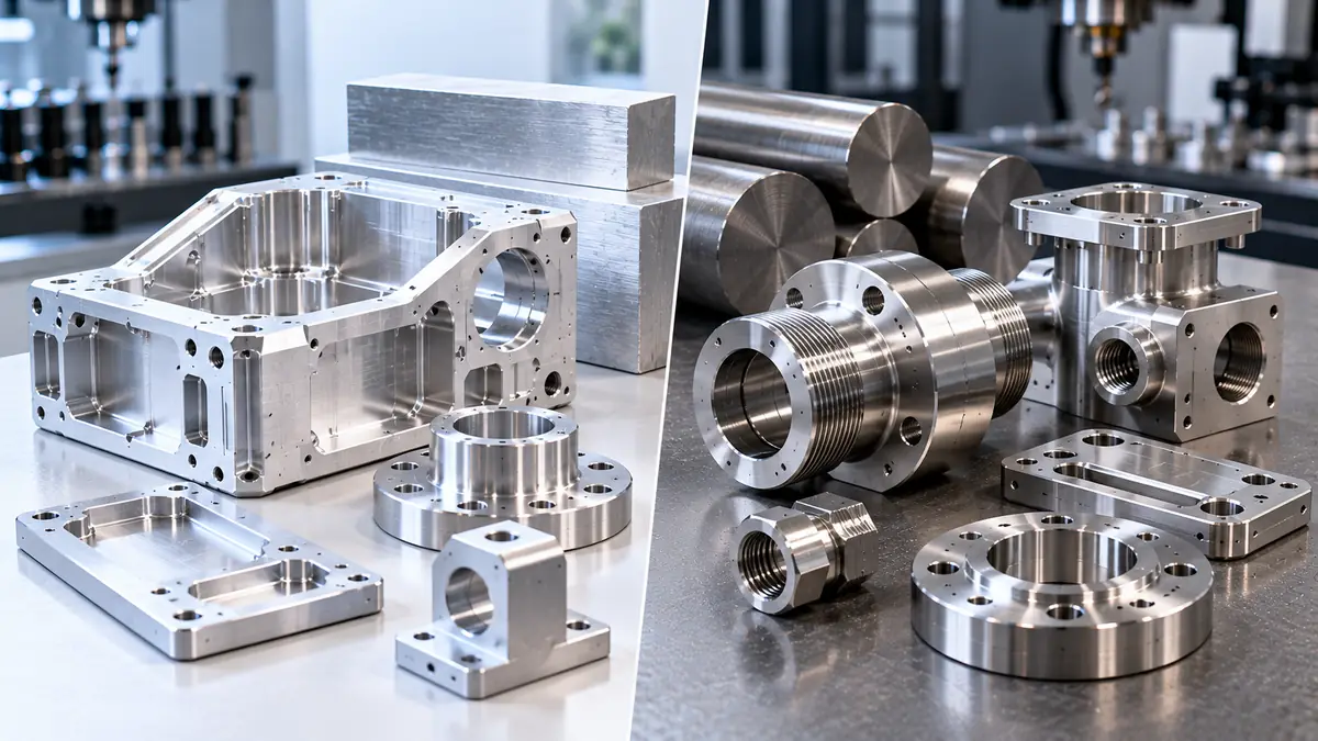
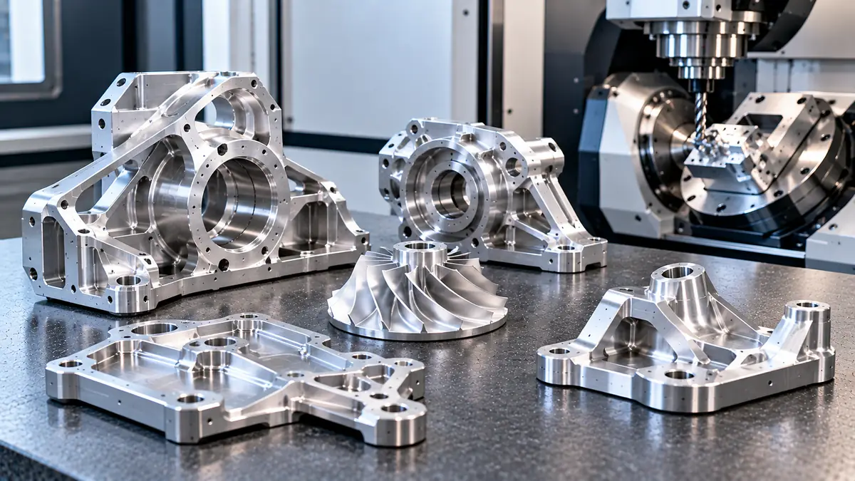
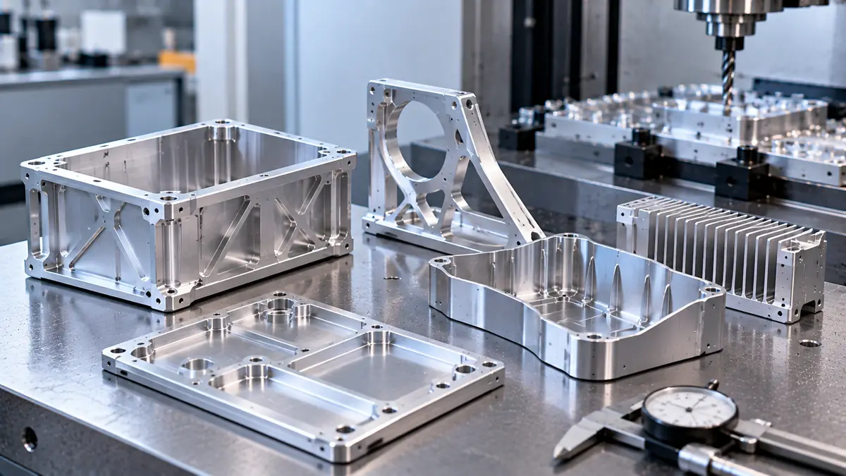
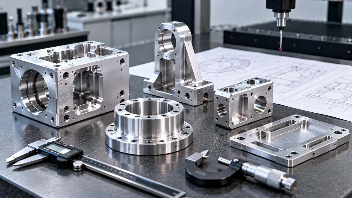
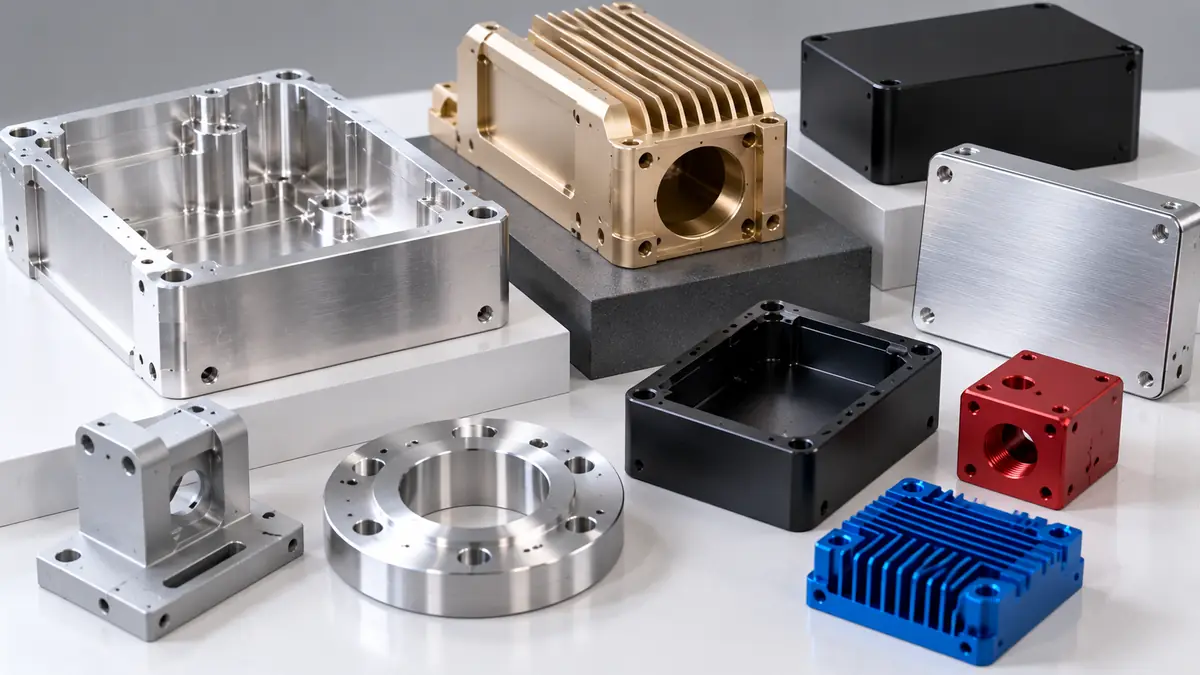
Besoin de solutions d'usinage expertes ? L'équipe de Tuowei Proto est là pour répondre à tous vos besoins en matière de fabrication. Contactez-nous dès aujourd'hui pour un devis sur vos projets en cours ou à venir !
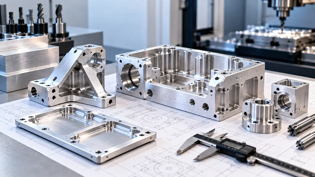
To design aluminum parts for CNC machining, shape every feature around the cutting tool that has to make it. Give internal corners a radius a standard end mill can reach, keep pockets shallow enough for a stiff tool, and make walls thick enough not to chatter. Use standard hole and thread sizes, and put tight tolerances only on the features that need them.
Short answer: Good aluminum DFM means using standard tool sizes, generous internal radii, moderate pocket depths, walls sized for their height, standard holes and threads, and as few setups as possible. Apply general tolerances such as ISO 2768-m to most dimensions, tight limits only to fits, and plan allowances for any anodized surface.
The guidelines below explain the reason behind each rule, because once you know why a rule exists you can judge when it is safe to bend it.
Design for manufacturability, or DFM, is the habit of shaping a part so it can be made reliably and at a sensible cost without losing any function. On a CNC machined part, almost every cost comes from three things: how long the spindle runs, how many times the part has to be re-clamped, and how much inspection the drawing demands.
Aluminum makes design for manufacturability easier than steel in one way and harder in two. It cuts fast. That makes a well-designed aluminum part cheap to run. But it is soft and can smear onto tools when features force slow, light cuts. It also carries residual stress from rolling and heat treatment, so thin or one-sided parts can move after they come off the machine.
Most aluminum DFM problems are settled in CAD, long before a quote arrives. A feature that takes ten seconds to model can add minutes to every cycle for the life of the part.
| Fonctionnalité | Design guideline | Pourquoi est-ce important ? |
| Internal corners | Radius slightly larger than a standard end mill radius | A rotating tool cannot cut a sharp inside corner |
| Pocket depth | Keep it to a few cutter diameters; step deep pockets | Tool deflection rises steeply with stick-out |
| Walls and floors | Size thickness to wall height; add ribs to tall walls | Thin walls chatter and move when stress is released |
| Trous | Standard drill sizes; through holes where possible | Stocked tools, better chip clearance, no special tooling |
| Threads | Standard UNC, UNF or metric sizes; only as deep as needed | Deep threads add cycle time and tap-breakage risk |
| Setups | Put features on as few faces as possible | Each re-clamp adds time and position error |
| Sous-coupes | Avoid, or match a standard T-slot or dovetail cutter | Special cutters are slow and fragile |
| Tolérances | ISO 2768-m or similar general note; tight limits on fits only | Tight tolerances slow the cut and add inspection |
| Finition de surface | As-machined unless function needs finer | Finer finishes need extra passes |
| Edges | One general edge-break note (ISO 13715) | Stops sharp burrs and debate at inspection |
| Anodized features | Allow for coating growth on bores, fits and threads | Coatings change dimensions |
Treat this table as a list of questions to ask about each feature, not a set of fixed numbers. The sections below give the reasoning and the limits.
Search for CNC design rules and you will find one guide recommending pockets up to 3 times the tool diameter, another 4 times, another 6. Minimum wall figures vary too. None of them is wrong. Each reflects what a particular shop can do with its own machines and tools.
The underlying physics is the same everywhere, and it explains why the numbers are close but not identical.
Tool stick-out. An end mill behaves like a cantilever beam. Its deflection under the same cutting force rises with the cube of its length. Double the stick-out and the tip bends eight times as much, so the shop has to cut lighter and slower to hold size.
Tool diameter. Tool stiffness depends on the fourth power of diameter. Halve the diameter and the tool becomes sixteen times more flexible. Put both together, a tool half as wide and twice as long, and you lose a factor of 128 in stiffness.
Wall thickness. A thin wall bends like a plate or beam, and its bending stiffness scales with the cube of thickness. A 1 mm wall is one-eighth as stiff as a 2 mm wall of the same height, which is why thin walls chatter and leave poor finishes.
Our view: use published aluminum DFM numbers as a starting point, then check each deep or thin feature with the shop that will make it. A two-minute question during design costs far less than a slow, fragile toolpath repeated on every part.
Material choice sets the rules for every other decision in aluminum part design. For most machined aluminum parts, 6061-T6 is the default: it machines easily, anodizes cleanly and costs less than the high-strength grades.
Stock size matters as much as alloy. A part that finishes at 25 mm thick can often be cut from standard 1 in. (25.4 mm) plate with a light facing pass. Make it 26 mm and the shop has to buy thicker plate and machine the extra away. Check the nearest standard bar or plate size before you fix the envelope.
A rotating cutter always leaves a radius in an internal vertical corner equal to at least its own radius. A 6 mm end mill cannot cut a corner tighter than 3 mm; a 1/4 in. end mill cannot go below 0.125 in.
Design the internal corner radius slightly larger than the radius of a standard tool. A 3.5 mm corner lets a 6 mm tool sweep through the corner in an arc. A corner that exactly matches the tool radius forces the tool to wrap the full corner at once, which raises cutting load and often leaves chatter marks.
Standard end mill diameters follow common series: 3, 4, 6, 8, 10 and 12 mm in metric, and 1/8, 3/16, 1/4, 3/8 and 1/2 in. in inch sizes. Choosing corner radii that suit these sizes keeps the shop on stocked tools, one of the simplest design for manufacturability wins.
Two related details:
The costly version of this mistake is a large pocket with 0.5 mm internal corners. The shop has to finish the whole pocket with a tiny, flexible tool, and cycle time multiplies.
Pocket depth is really a question about the tool that has to reach the floor. As the stick-out numbers above show, a deep pocket with small corner radii forces a long, thin tool, the worst combination for stiffness.
Practical ways to keep pockets machinable when designing aluminum parts:
When a deep, narrow feature cannot be avoided, a shop may use long-reach or reduced-shank tools, or switch to wire EDM. Both work, but both cost more per feature, so reserve them for features that truly need the depth.
Thin walls are one of the most common reasons an aluminum part quotes high or comes back out of tolerance. Because stiffness scales with the cube of thickness, a tall, thin wall deflects away from the cutter, rings as the tool passes and springs back after the cut.
In aluminum part design, size wall thickness to wall height. A short thin wall is usually fine; the same thickness on a tall wall may not be. Adding a rib, a lip at the top or a connection to a neighboring wall can transform a flimsy wall at almost no cost.
Thin floors behave the same way. A large, thin pocket floor vibrates like a drum skin. Break it up with ribs or leave it thicker and use a separate cover if weight allows.
Residual stress adds a second problem. When most of the material comes off one side of a plate, the remaining stress can bow the part after it is unclamped. Aluminum part designs with roughly balanced material removal on both sides, cut from T651 stretched plate, stay flatter. Shops often rough, release the clamps and then finish to control this, and our CNC milling services team plans that sequence for thin-walled parts.
In aluminum DFM, holes are cheap when they match stocked tools and expensive when they do not.
For threads, stay with standard series: UNC and UNF for inch parts, ISO metric coarse or fine for metric parts. Specify the thread by standard designation and class rather than by drawing the thread form.
When designing aluminum parts, thread depth deserves more thought than it usually gets:
Thread milling is an option for large or critical threads and removes the risk of a broken tap in a finished part. It is slower on small threads. Unless the drawing needs it, let the shop choose.
Every time a part is unclamped and turned to reach another face, the shop spends setup time and adds a small position error between features on different faces. Keeping related features on the same face, or reachable from the same direction, cuts both.
A useful habit in aluminum CNC design is to model the part as the machinist will see it: which face goes down first, what the vise grips, and what is left for the second setup. If a part needs features on four or five faces, a Usinage CNC à 5 axes setup can often reach most of them in one clamping, which improves feature-to-feature accuracy even if the hourly rate is higher.
Undercuts are features a straight tool cannot reach from above: O-ring grooves inside a bore, T-slots, dovetails. They can be cut with T-slot, dovetail or lollipop cutters, but those tools are slow and fragile. If you need an undercut, size it to match a standard cutter width and leave clearance above it for the tool shank.
Good aluminum CNC design leaves room for workholding too. A part with no flat, parallel surfaces for a vise to grip may need custom soft jaws or a fixture plate, which adds cost on small orders. Sometimes a sacrificial tab or extra stock that is cut off at the end is the cheapest solution.
Tolerances are where aluminum part design most often adds cost without adding function. Tight limits force slower finishing passes, in-process measurement and more inspection time.
Put a general tolerance note on the drawing and apply it to every dimension that is not specially toleranced. ISO 2768-1 is the most widely used, with four classes: fine (f), medium (m), coarse (c) and very coarse (v).
| Nominal length | ISO 2768-f | ISO 2768-m |
| Over 6 up to 30 mm | ±0.1 mm | ±0.2 mm |
| Over 30 up to 120 mm | ±0.15 mm | ±0.3 mm |
| Over 120 up to 400 mm | ±0.2 mm | ±0.5 mm |
For most machined aluminum parts, ISO 2768-m is a sensible default; move individual features tighter only when a fit or function requires it.
For bores and shafts that mate, use a standard fit from ISO 286-2 rather than an arbitrary tolerance. A Ø20 H7 bore, for example, is 0 to +0.021 mm. Machinists recognize these callouts and have reamers and gauges to match.
Where the position between features matters more than individual sizes, use geometric dimensioning and tolerancing (GD&T) per ASME Y14.5. A position tolerance tied to clear datums often allows more manufacturing freedom than a stack of tight plus-or-minus dimensions while controlling what actually matters.
One practical limit: tolerances between features machined in different setups are harder to hold than tolerances within one setup. If two holes must be precisely positioned relative to each other, design them so both can be machined from the same side.
Tuowei’s standard as-machined finish is about 125 µin Ra (3.2 µm), with visible tool marks. That is fine for most functional surfaces. Finer finishes need extra passes, so call them out only on sealing faces, sliding surfaces, cosmetic faces or fatigue-critical radii.
Edges need a rule too. Without one, some edges come back razor sharp and others heavily chamfered. A single general note based on ISO 13715, which defines how to indicate edges of undefined shape, tells the shop how much burr is acceptable and how much edge break is expected.
Anodizing is where aluminum DFM overlaps with finishing. If the part will be anodized, plan the dimensions for the coating. MIL-PRF-8625, the US anodizing specification, states that each coated surface grows by about half the coating thickness. For a hard anodized (Type III) coating at its nominal 0.002 in., that means about 0.001 in. per surface, or about 0.002 in. on a diameter. Bores shrink, shafts grow and threads tighten. Either machine those features to allow for growth, mask them, or state that dimensions apply after coating.
Cosmetic parts often get bead blasting before anodizing to hide tool marks. Put it on the drawing if you want it, because an anodized clear coat shows every tool mark underneath.
These come up again and again in RFQs (requests for quote):
Most of these aluminum DFM mistakes take seconds to fix in CAD and hours to fix after the first article inspection.
Run through this aluminum DFM checklist before you send the files:
When the package is ready, our Services d'usinage CNC team reviews it for manufacturability before quoting, and flags features that add machine time without adding function.
The fastest way to design aluminum parts for CNC machining well is to picture the tool reaching each feature: how long it has to be, how wide it can be, and how many times the part has to be turned over to get there. Most DFM guidelines follow from those three questions.
For fatigue-critical and aerospace components, the same design for manufacturability rules matter even more, because a sharp corner or poor finish on a loaded radius can shorten the part’s life as well as raise its price. If you want a second pair of eyes on a design, send the model and drawing to Précision Tuowei and our engineers will review it before any metal is cut.
Q: What is the minimum wall thickness for CNC machined aluminum?
A: There is no single number. The safe minimum depends on wall height, alloy and whether the wall is supported. Because stiffness scales with the cube of thickness, a thin wall that works at low height may chatter when tall. Add ribs to tall walls and confirm the minimum with your machinist.
Q: What tolerances can CNC machining hold on aluminum?
A: Most dimensions only need a general class such as ISO 2768-m, which allows ±0.2 mm from 6 to 30 mm and ±0.3 mm from 30 to 120 mm. Fits can be held much tighter, for example an H7 bore, but each tight tolerance adds machining and inspection time.
Q: Can CNC machining make sharp internal corners?
A: Not with a rotating end mill. The tool always leaves a radius at least equal to its own radius. Design internal corners slightly larger than a standard tool radius, and use dog-bone reliefs where a square part must seat fully. Truly sharp corners need wire EDM, which costs more.
Q: How deep can a CNC machined pocket be?
A: It depends on the tool that must reach the floor. Tool deflection rises with the cube of stick-out, so deep pockets with small corner radii force slow, light cuts. Keep pockets to a few cutter diameters deep, step deep pockets, and increase corner radii where depth is unavoidable.
Q: What should be included in an RFQ for an aluminum CNC part?
A: Send a STEP file and a 2D PDF drawing with the revision, alloy and temper, a tolerance note, critical dimensions, finish and coating requirements, quantity breaks and inspection needs. A complete package gets a faster, more accurate quote and fewer surprises at first article inspection.

Written by Andy, Manufacturing Engineer at TUOWEI Precision. Andy specializes in CNC machining, precision manufacturing, and production engineering, with hands-on experience supporting projects from rapid prototyping through full-scale production. He works closely with engineering and manufacturing teams to evaluate materials, tolerances, machining processes, and design manufacturability. His articles provide practical, technically informed insights to help engineers and buyers make better manufacturing decisions, optimize production efficiency, and achieve consistent part quality. Explore TUOWEI Precision’s CNC machining and custom manufacturing solutions for your next project.
From rapid prototypes to scalable production, Tuowei Precision delivers reliable CNC machining with accuracy and consistency at every step. Start your project today.
Tenez-vous au courant de l'usinage CNC réel, des tendances de l'industrie et des perspectives de production de Tuowei Precision, qui est installé pour vous permettre de prendre de meilleures décisions en matière de production.