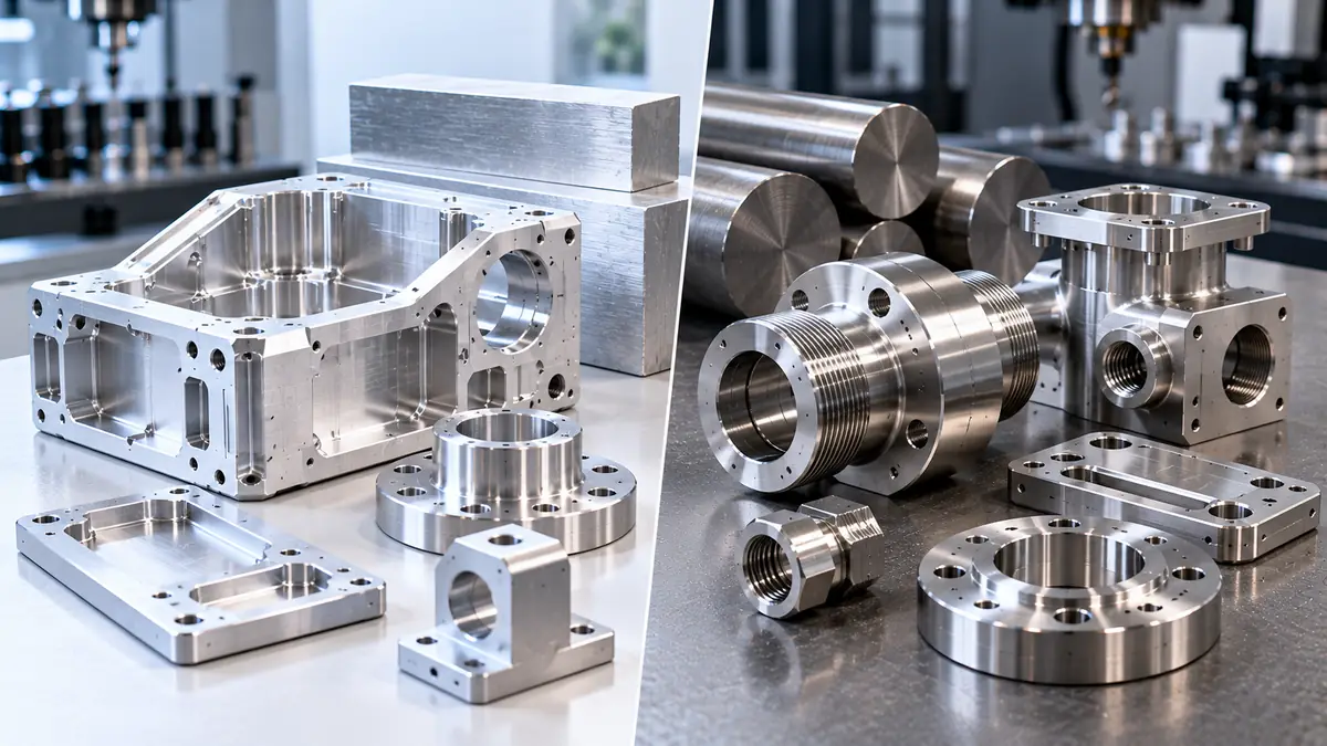
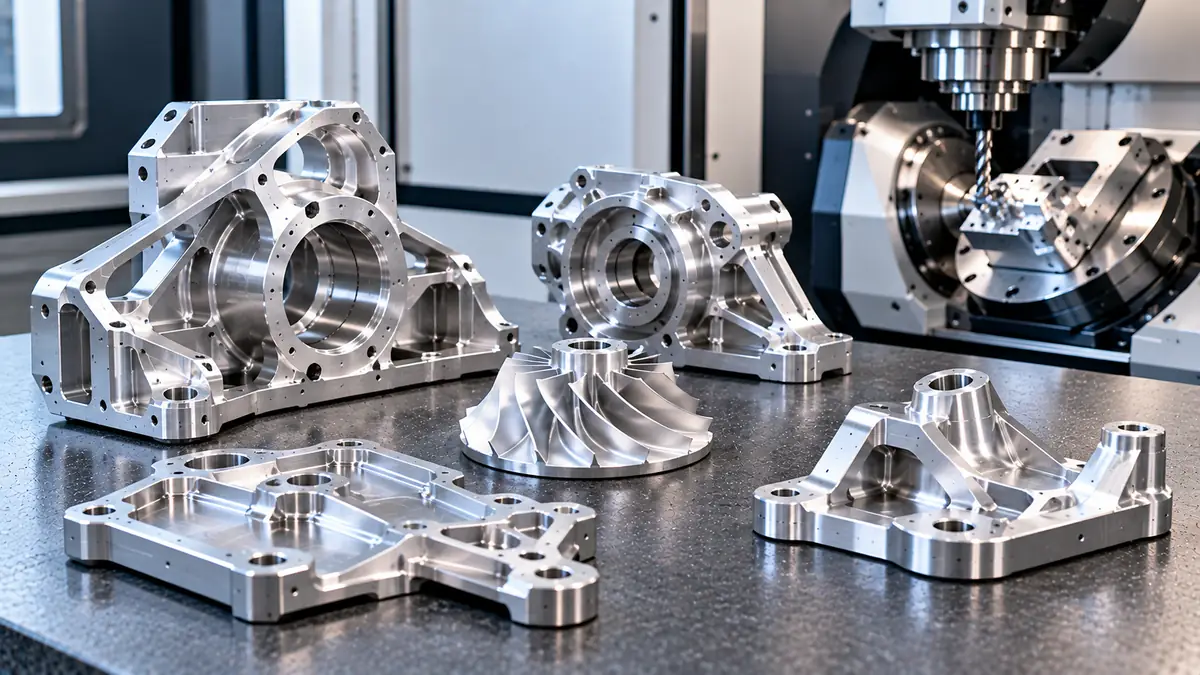
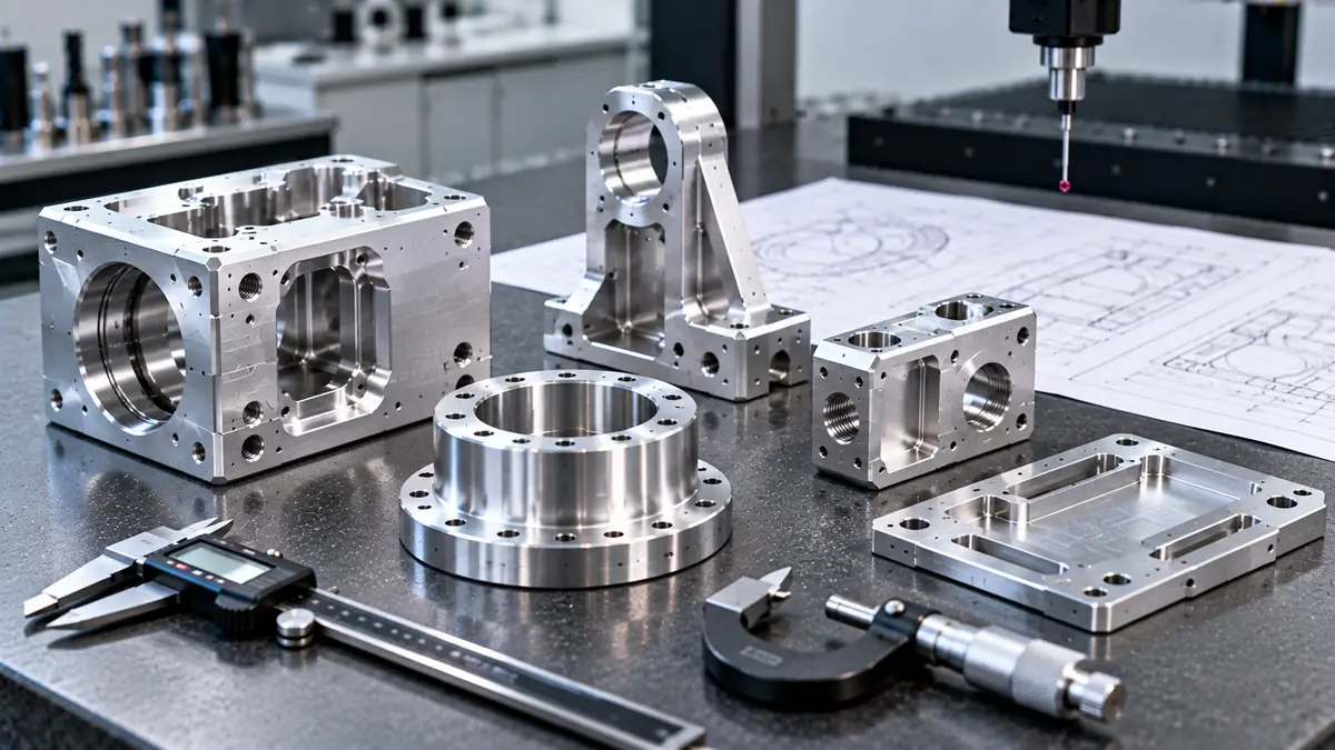
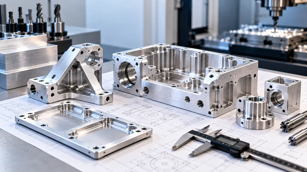
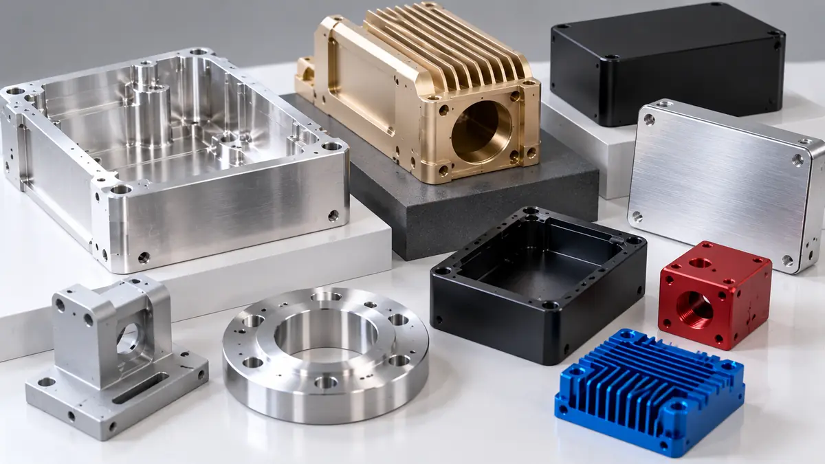
Besoin de solutions d'usinage expertes ? L'équipe de Tuowei Proto est là pour répondre à tous vos besoins en matière de fabrication. Contactez-nous dès aujourd'hui pour un devis sur vos projets en cours ou à venir !
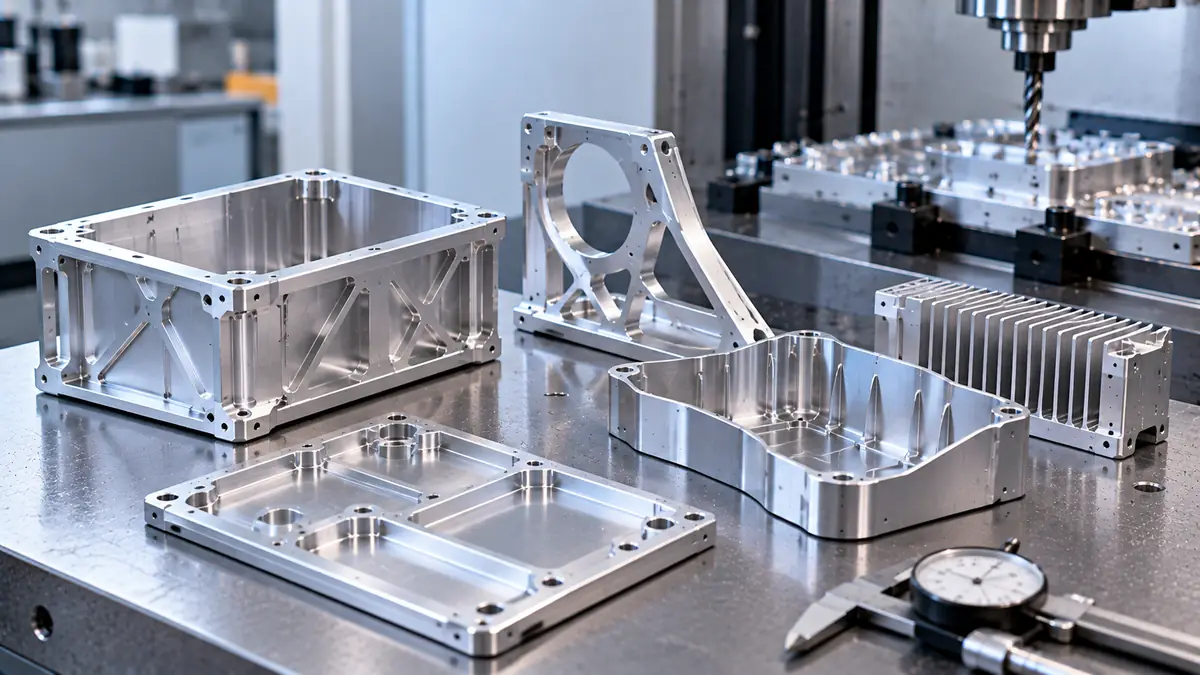
Thin-wall aluminum machining goes wrong in two ways. The wall vibrates while it is being cut, which leaves chatter marks and a wavy surface. Or the part moves after it comes off the machine, because internal stress was released unevenly or the clamps bent it. Both are controlled the same way: keep the wall supported for as long as possible, cut with light and even forces, and start from stress-relieved stock.
Short answer: To prevent warping, use stress-relieved T651 plate, remove material evenly from both sides, rough everything before finishing, and hold the part without forcing it flat. To prevent chatter, use the shortest, sharpest tool that reaches, take light radial finishing cuts, finish tall walls in steps from the top down, and tune spindle speed.
The rest of this guide explains why each of those steps works, with the physics behind them, so you can judge which ones a particular part needs.
There is no universal number. Published guides call a wall “thin” below 2 mm, below 1.5 mm, or above a height-to-thickness ratio anywhere from 10:1 to 20:1. The disagreement makes sense once you see that thickness alone does not decide how a wall behaves.
What matters is stiffness, and stiffness depends on both height and thickness. A wall standing up from a pocket floor behaves roughly like a cantilever beam. Under a sideways cutting force at its free edge, its deflection rises with the cube of its height and falls with the cube of its thickness.
So a 1 mm wall 5 mm tall may machine easily. At 40 mm tall, the same wall is a real problem. In practice, a wall is “thin” when the cutting force is large enough, relative to its stiffness, to push it out of position or set it vibrating.
That is why this guide treats thin aluminum walls by height and thickness together rather than by a single minimum.
Five mechanisms cause almost every problem with thin-walled parts. They show up at different moments, which is the quickest way to tell them apart.
| Cause | What you see | When it shows up | Main fix |
| Cutting-force deflection | Wall thicker at the top than planned, taper | During the cut; measures wrong on the machine | Lighter radial cuts, finish in steps from the top down |
| Chatter (self-excited vibration) | Wavy marks, noise, poor finish | During the cut | Shorter tool, tuned spindle speed, more support |
| Residual stress release | Part bows or twists after unclamping | After the part is released | T651 stock, balanced removal, rough-rest-finish |
| Clamping distortion | Part springs out of flat after unclamping | When clamps come off | Even, lower clamping force, vacuum or conformal support |
| Heat | Size drifts during the cut, then changes as it cools | During and just after the cut | Coolant, sharp tools, measure at a stable temperature |
Two of these, stress and clamping, only appear after the part is released. A part can look perfect on the machine and still fail inspection. That is also why “warping” and “chatter” need different fixes: one is a static problem of stress and support, the other a dynamic problem of vibration.
Two simple relationships from beam theory explain most thin-wall behavior.
Deflection. For a wall treated as a cantilever, deflection under the same force is proportional to height cubed divided by thickness cubed. Double the height and deflection rises eight times. Halve the thickness and it also rises eight times.
Natural frequency. The first natural frequency of the wall, the frequency at which it prefers to vibrate, is proportional to thickness divided by height squared. Halve the thickness and the frequency halves. Double the height and it drops to a quarter.
The table below uses the cantilever formula for a 6061 aluminum wall, with a modulus of 68.9 GPa (10.0 × 10³ ksi, from the NASA 6061 handbook) and a density of 2.70 g/cm³. Real walls joined to other walls or corners are stiffer than this idealized case, so treat the numbers as a comparison, not a prediction.
| Epaisseur de la paroi | Wall height | Approximate first natural frequency |
| 2 mm | 20 mm | 4,080 Hz |
| 1 mm | 20 mm | 2,040 Hz |
| 2 mm | 40 mm | 1,020 Hz |
| 1 mm | 40 mm | 510 Hz |
Now compare that with the cutter. The tooth-passing frequency is spindle speed times number of flutes divided by 60. A three-flute end mill at 12,000 RPM hits the wall 600 times a second, or 600 Hz. The tall 1 mm wall at 510 Hz sits close to that forcing frequency, while the short 2 mm wall is far above it.
This is the practical meaning of “thin.” As a wall gets taller and thinner, its natural frequency falls toward the range the cutter is exciting, and small changes in speed or depth start to matter a lot. It also explains why milling thin walls gets harder so quickly as they grow taller.
One more point that surprises designers: switching from 6061 to 7075 does not make a wall stiffer. The NASA handbooks list moduli of 10.0 and 10.3 × 10³ ksi for the two alloys, only about 3% apart. 7075 is much stronger, but a wall that flexes in 6061 will flex almost as much in 7075.
Chatter is a self-excited vibration. Each tooth leaves a slightly wavy surface. The next tooth meets that wave, and if the timing is wrong, the vibration grows with every pass. On thin-walled aluminum parts, the vibrating part may be the wall rather than the tool, and the wall’s behavior changes as material comes off.
Machinists map where cutting is stable using a stability lobe diagram, which plots the maximum chatter-free depth of cut against spindle speed. The stable “lobes” sit at speeds where the tooth-passing frequency lines up with a whole-number fraction of the system’s natural frequency. NIST researchers showed that these stability limits also shift with tool overhang length, and that tuning the overhang can raise the chatter-free material removal rate (Schmitz et al., NIST).
In practice, these are the levers:
Spindle speed advice varies by machine, holder and tool. A speed that works on one machine may chatter on another. A tap test, which measures the tool’s frequency response with an instrumented hammer, gives the real stability lobe for a specific setup.
Rolled aluminum plate is quenched after solution heat treatment, and the fast cooling locks stress into it: compression near the surfaces, tension in the middle. While the plate is whole, these stresses balance. Machine away material unevenly and the balance breaks, so the remaining part bends to find a new equilibrium. That is machining distortion, and it often appears only after the part is unclamped.
The first line of defense is the material form. Under the Aluminum Association’s temper system (ANSI H35.1), a “51” suffix such as T651 means the product was stress relieved by stretching after solution heat treatment, with a permanent set of 1½ to 3% for plate. That stretch evens out much of the quenching stress, which is why 6061-T651 and 7075-T651 plate stay flatter after heavy pocketing than unstretched material.
Our position: for any thin-walled aluminum part cut from plate, specify T651. The small premium is far cheaper than scrapped parts.
Strategy matters as much as stock:
Heat treating to relieve stress is limited for T6 and T651 aluminum. Heating near or above the aging temperature changes the temper and lowers strength, so thermal stress relief should only be used if the heat treatment and properties are approved for the part.
The same logic applies to thin-wall parts cut from extrusions or forgings. The stress pattern is different, but uneven removal still releases it unevenly, and the same balanced sequence still helps.
Stock form decides how much stress a part starts with, which makes it the first defense against machining distortion. For thin-walled aluminum parts, the temper suffix is the quickest guide:
Alloy matters less than form here. 6061-T651 is the default for machining thin walls in aluminum; 7075-T651 adds strength, not stiffness.
Clamping can cause as much distortion as cutting. A thin plate forced flat against a fixture will be flat while clamped, then spring back when released, with the errors cut into it in the wrong places.
Good fixturing for thin-wall parts spreads force and supports the part where the tool is pushing:
For thin-walled aluminum parts such as the enclosures and housings used in électronique grand public, the usual approach combines two setups: rough the outside while holding the solid blank, then hold the part by its roughed features, or in a vacuum or conformal fixture, to finish the thin walls.
When machining thin walls, toolpath choice decides how force is applied to the wall, which makes it the cheapest place to reduce both deflection and chatter.
Tool deflection and wall deflection add together. A long, thin tool bending away from a thin wall that is also bending away can leave a wall much thicker at the top than the program says. Our CNC milling services team plans the step-down sequence and tool lengths together for this reason, and checks wall thickness during the job rather than only at final inspection.
Aluminum conducts heat well, but thin aluminum walls have very little mass to absorb it. Heat from the cut raises the wall’s temperature quickly, so the wall grows while it is being finished and shrinks as it cools. The result is a part that measured correctly on the machine and reads undersize or distorted on the bench.
Ways to keep the temperature steady:
For thin-walled parts that must be machined dry, expect lighter cuts and more time between roughing and finishing.
Often, yes. A Usinage CNC à 5 axes setup helps thin-walled parts in two ways.
First, it can reach several faces in one clamping. Every re-clamp is a new chance to distort thin-wall parts, so fewer setups means fewer clamping errors and better alignment between features.
Second, tilting the tool or the part lets the machine reach deep walls with a shorter tool. Since tool stiffness drops quickly with overhang, a shorter tool is one of the most effective chatter fixes available.
The trade-off is a higher hourly rate and more programming time. For a simple thin plate with features on one side, a well-fixtured 3-axis setup is usually the better value.
Thin-walled aluminum parts turned on a lathe, such as rings, sleeves and round housings, add a problem that milled parts do not have: the chuck. A standard three-jaw chuck squeezes a thin ring at three points. The ring is turned round while clamped, then springs back into a slightly three-lobed shape when it is released.
Common fixes:
The principle is the same as machining thin walls on a mill: spread the holding force, and never ask the fixture to hold the part in a shape it does not want to keep.
Many problems with thin aluminum walls can be removed at the design stage for almost no cost.
Pour aerospace components, where weight targets push thin aluminum walls thinner still, these choices usually decide whether a part can be made repeatably at all.
Thin-walled parts can pass or fail inspection depending on how they are held while measured. A part flexible enough to change shape under its own weight, or under a light clamp, is what the standards call a non-rigid part.
ISO 10579 covers how to dimension and tolerance non-rigid parts. It lets the drawing state whether a requirement applies in the free state, with the part unrestrained, or in a restrained condition that imitates how it will be held in assembly. ASME Y14.5 uses a free-state symbol for the same purpose. Without that note, the shop and the customer may measure the same part two different ways and get two different answers.
Temperature matters too. ISO 1 sets 20 °C as the standard reference temperature for dimensional specifications. Thin aluminum parts warm quickly during cutting and cool quickly afterward, so they should reach a stable room temperature before final measurement.
Practical inspection steps:
These patterns most often turn thin-wall parts into scrap:
Most of these cost nothing to fix once the cause is understood. The difficult part is diagnosing which mechanism is at work, which is why noting when the problem appears, during the cut or after release, is the first step.
Successful thin-wall aluminum machining comes from treating the wall as a flexible structure through the whole process. Start with stretched T651 stock, rough evenly and let the part settle, hold it without forcing it, and finish with short, sharp tools in steps that keep the thin section supported.
If you have a thin-walled housing, bracket or aerospace part to quote, send the model and drawing to Précision Tuowei. Our engineers will review wall heights, fixturing and inspection conditions before cutting, and our Services d'usinage CNC cover both prototypes and production runs.
Q: What is the minimum wall thickness for machining aluminum?
A: There is no single minimum, because wall height matters as much as thickness. Deflection rises with height cubed and falls with thickness cubed, so a short 1 mm wall can machine easily while a tall one chatters. Add ribs to tall walls and confirm limits with your machinist for each geometry.
Q: How do you prevent chatter when milling thin walls?
A: Use the shortest, sharpest tool that reaches, take light radial finishing cuts, and finish tall walls in steps from the top down so stock below supports the cut. If chatter persists, change spindle speed up or down, try a variable-pitch end mill, or support the wall with a filler.
Q: Why do thin-wall aluminum parts warp after machining?
A: Usually because residual stress from quenching is released unevenly, or because clamping forced the part flat during cutting. Using stretched T651 plate, removing material evenly from both sides, and releasing the clamps after roughing before the finish pass all reduce the movement.
Q: How do you hold thin-wall parts without distorting them?
A: Spread the holding force. Vacuum fixtures, soft jaws shaped to the part, fitted inserts and sacrificial tabs all hold without point pressure. Tighten clamps evenly and only as much as the cut needs, because an over-clamped thin part springs back out of shape when it is released.
Q: Is climb milling better for thin walls?
A: Usually for finishing aluminum, because the chip goes from thick to thin and the tool rubs less, which improves finish. On a very flexible wall, the direction the cutting force pushes the wall also matters, so confirm the choice on a first part before running production.

Written by Andy, Manufacturing Engineer at TUOWEI Precision. Andy specializes in CNC machining, precision manufacturing, and production engineering, with hands-on experience supporting projects from rapid prototyping through full-scale production. He works closely with engineering and manufacturing teams to evaluate materials, tolerances, machining processes, and design manufacturability. His articles provide practical, technically informed insights to help engineers and buyers make better manufacturing decisions, optimize production efficiency, and achieve consistent part quality. Explore TUOWEI Precision’s CNC machining and custom manufacturing solutions for your next project.
From rapid prototypes to scalable production, Tuowei Precision delivers reliable CNC machining with accuracy and consistency at every step. Start your project today.
Tenez-vous au courant de l'usinage CNC réel, des tendances de l'industrie et des perspectives de production de Tuowei Precision, qui est installé pour vous permettre de prendre de meilleures décisions en matière de production.