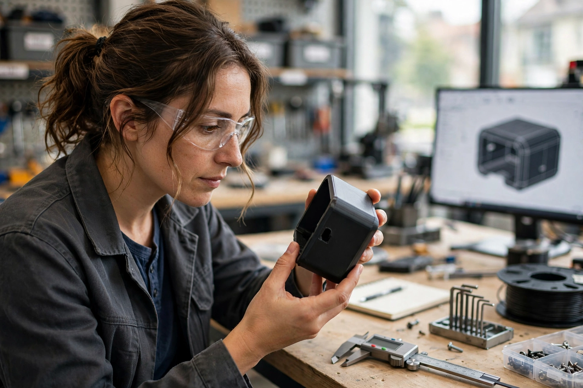
If you are asking what is rapid prototyping, the short answer is a physical version of a part built early, so a design can be tested before production tooling is cut. Teams use our dedicated prototyping service to check fit, form, and function, catch design mistakes while still cheap to fix, and show stakeholders something real instead of a drawing.
If you are developing a new enclosure, bracket, or housing, a prototype lets you hold the part, fit it against mating components, and test how it behaves in use. The same term is also used in UX and software design, while this guide covers physical parts. It is written for buyers of custom parts and designers alike.
Prototyping starts with a simple idea: a group of techniques used to quickly fabricate a physical part or assembly from a three-dimensional design, turning a concept into something testable. The goal of rapid prototyping is speed of learning: instead of waiting for production tooling, a team builds a model in days, tests it, and feeds what it learns back into the design. The term covers many methods, from 3D printing to CNC machining and casting.
The word rapid refers to the cycle as much as to the build. A prototype that takes a week but saves a month of rework is rapid in the sense that matters. What counts is how fast a team can move from an idea in product design to a tested part, and then to a better version of that part.
In rapid prototyping, the process follows the same loop in most projects, whatever method builds the part. An initial design is modeled in CAD, the model is prepared for the chosen process, the part is built, and the result is tested against the design intent. Each loop answers specific questions at different stages of development, and the design changes after every round until it is ready for production.
The number of loops matters more than the speed of any single build. Early loops test shape and fit with cheap methods, while later loops test function with production-like materials. Skipping the cheap loops is a common mistake: it moves cost from prototypes into production rework.
Every prototype starts as a three-dimensional computer-aided design (CAD) model. The model defines the geometry, wall thickness, and design elements the prototype must reproduce. Designs made for production often need adjustment for prototyping, such as thicker walls for printed parts or added stock for machined ones.
A second check at this stage saves rebuilds: wall thickness, draft, and minimum feature size should match the chosen method before any build starts. A wall that prints fine can still be too thin to machine, and a feature that machines well can still trap resin in a print.
The method is chosen by what the prototype must prove: shape, fit, function, or appearance. Printed parts suit low-fidelity shape and early fit checks, while machined or cast parts suit functional testing and high-fidelity look and feel. The build itself may take hours for a printed part or days for a machined one, depending on size and complexity.
This is where method knowledge pays off: in rapid prototyping, the same CAD file can produce very different parts depending on the method, so the choice should be recorded with the reason behind it. That record keeps later loops honest about what changed and why.
The prototype is measured against the CAD model, fitted with mating parts, and tested under realistic conditions. Failures feed back into the design process as changes, not as wasted work: each failed prototype removes a defect that would have been far more expensive to fix after production tooling was cut.
Testing should match the question the loop was meant to answer. A fit check needs dimensional measurement, while a functional test needs load, heat, or use cycles. Testing a prototype for the wrong property produces confidence without evidence, so define what each test must validate before building.
| Process step | What happens | What it answers |
|---|---|---|
| 1. Digital model | Geometry, wall thickness, and features are defined in three dimensions | Is the design complete and buildable? |
| 2. Build | The part is printed, machined, cast, or formed by the chosen method | Can the design be made at all? |
| 3. Test | The part is measured, fitted with mating parts, and used under realistic conditions | Does it fit, work, and feel right? |
| 4. Refine | Findings become design changes and the next loop begins | What must change before production? |
Prototypes differ by what they are meant to prove, and naming the type keeps a project honest about what a test result means. A model that proves a shape cannot prove strength, and a model that proves a function cannot prove market appeal. The table below lists the types most teams use, in the order they usually appear.
| 種類 | What it proves | Typical method |
|---|---|---|
| Proof-of-concept | That the idea can work at all | Rough 3D print or simple mockup |
| Looks-like | Appearance, size, ergonomics, and feel | High-detail print or finished model |
| Works-like | Function, fit, and performance under use | CNC machined part or cast part |
| Engineering / validation | Production readiness: tolerances, materials, assembly | Production-material machined or cast part |
In rapid prototyping, fidelity cuts across all four types. A low-fidelity model is rough and cheap, built to test one question fast; a high-fidelity model is close to the final part in look, material, or behavior, and costs more. Early loops usually stay low-fidelity, and fidelity rises as the design firms up and the questions get harder.
Most programs start with a proof-of-concept model to settle the riskiest question, then move to looks-like and works-like models as the design firms up. Engineering and validation builds come last, because they cost the most and only make sense once shape and function are settled.
Skipping ahead is the usual mistake. A validation build made before the shape is settled tests a design that is still changing, so the result is out of date before it is read.
In 3D printing, a prototype is built layer by layer from a digital model, adding material only where the design needs it. Because no mold or tooling is required, a new design can go from file to physical part quickly, which is why printing became the most visible form of prototyping. The ISO/ASTM 52900 standard defines additive manufacturing as joining materials from 3D model data, usually layer upon layer.
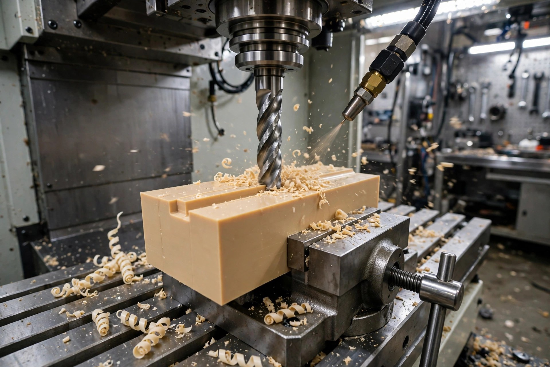
Printing is the best known method, but the field is wider. A prototype can also be machined from solid stock, cast in urethane, or formed from sheet metal. The right method depends on the material, tolerances, and tests the prototype must pass.
Print orientation changes strength and finish. Layers bond less strongly across the build direction than along it, so a part printed flat behaves differently from the same part printed upright. Ask your supplier which orientation was used before trusting a load test.
No single method suits every prototype. Additive methods build parts by adding material, and are fast and cheap for shape checks, machining gives real production materials and tight tolerances, and casting bridges the gap to small batches. Tool choice matters as much as the method; the table below compares the usual options. ISO/ASTM 52900 groups printing methods into seven process categories, so FDM, SLA, SLS, and MJF are standard category names rather than brand names.
| 方法 | How it works | こんな方に最適 | Watch out for | Standard category |
|---|---|---|---|---|
| 多重伝送装置 | Melted filament is laid down in thin layers | Cheap, fast shape and fit checks | Visible layer lines, lower detail | Material extrusion |
| エスエルエー | A UV laser cures liquid resin into solid layers | Fine detail and smooth surfaces | Smaller builds, resin handling | Vat photopolymerization |
| SLS | A laser fuses nylon powder into solid layers | Strong parts with no supports needed | Rougher surface, higher cost | Powder bed fusion |
| MJF | Fusing agent and heat bind powder layers | Fast builds with good detail | Limited material range | Powder bed fusion |
| CNC加工 | Material is cut away from solid stock | Real production materials and tight tolerances | Slower for complex shapes, more waste | Subtractive (outside AM) |
| Urethane casting | Resin is cast into silicone molds | Small batches of production-like parts | Mold cost, limited run sizes | Formative (outside AM) |
| Sheet metal prototyping | Sheet is cut, bent, and joined | Real sheet parts and enclosures | Limited to sheet geometries | Formative (outside AM) |
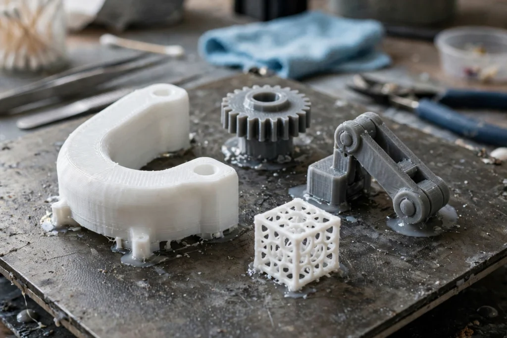
Printed accuracy varies, and buyers should plan for it. NIST lists insufficient part accuracy and surface finish, along with difficult repeatability, among the technical challenges for metal additive manufacturing. That is why functional prototypes are usually machined or measured against the CAD model rather than trusted on appearance.
The same caution applies to printed plastics. Layer lines, shrinkage, and orientation all shift dimensions, so a printed part that fits today may not match the production part tomorrow. Treat printed dimensions as indicative until a machined or cast version confirms them.
Design errors found after production tooling is cut are expensive to fix: molds must be reworked, schedules slip, and launched products may need recall or redesign. Prototyping moves that discovery earlier, when design flaws cost a revised file and a new prototype instead of a revised mold.
Prototyping also improves decisions that drawings cannot settle. Stakeholders react differently to a part they can hold, and assembly teams spot handling and user experience problems only when parts are real. A prototype turns opinions about a design into evidence about it. That evidence is the main return on rapid prototyping.
Skipping prototypes rarely saves money; it moves the cost. A design flaw found after tooling is cut means reworked molds, slipped schedules, and in the worst case a launched product that needs recall or redesign. The prototype loop is cheap insurance against that sequence.
The risk is highest on parts with tight fits, moving assemblies, or safety roles. For those, one untested assumption can cost more than the entire prototype program. If the budget is tight, protect the first loop and cut later ones.
The benefits fall into four groups: faster development, lower risk, better communication, and better final designs. Design teams iterate in days instead of waiting for tooling, test ideas for a new product that would be too risky to commit to production, and show customers and investors a working part instead of a rendering.
These benefits compound across loops. Each round removes uncertainty, so the production design starts from evidence rather than assumptions. Products that skip prototyping often pay for the same learning later, at production prices.
The clearest sign that rapid prototyping is working is a shorter list of open questions after each loop. Teams should record what each prototype proved and what it did not, because that record turns a shelf of old parts into design knowledge. Without it, the next project repeats the same tests.
That record also settles arguments faster. When a stakeholder questions a dimension or a material choice, the team can point to a tested part instead of debating a drawing. Evidence ends discussions that opinions only extend.
Traditional manufacturing starts with tooling: a mold or die is designed, cut, and tested before the first production part appears. That route suits high volumes, where tooling cost spreads across thousands of parts, but it makes early design changes slow and expensive. Rapid prototyping reverses the order by putting a testable part in hand before tooling is committed.
The two approaches are complements, not rivals. Prototyping answers design questions, and traditional manufacturing processes answer volume questions. A product that needs thousands of identical parts still needs production tooling, and rapid tooling can bridge short runs before that tooling is cut; prototyping simply makes sure that tooling is cut for a design already proven in physical form.
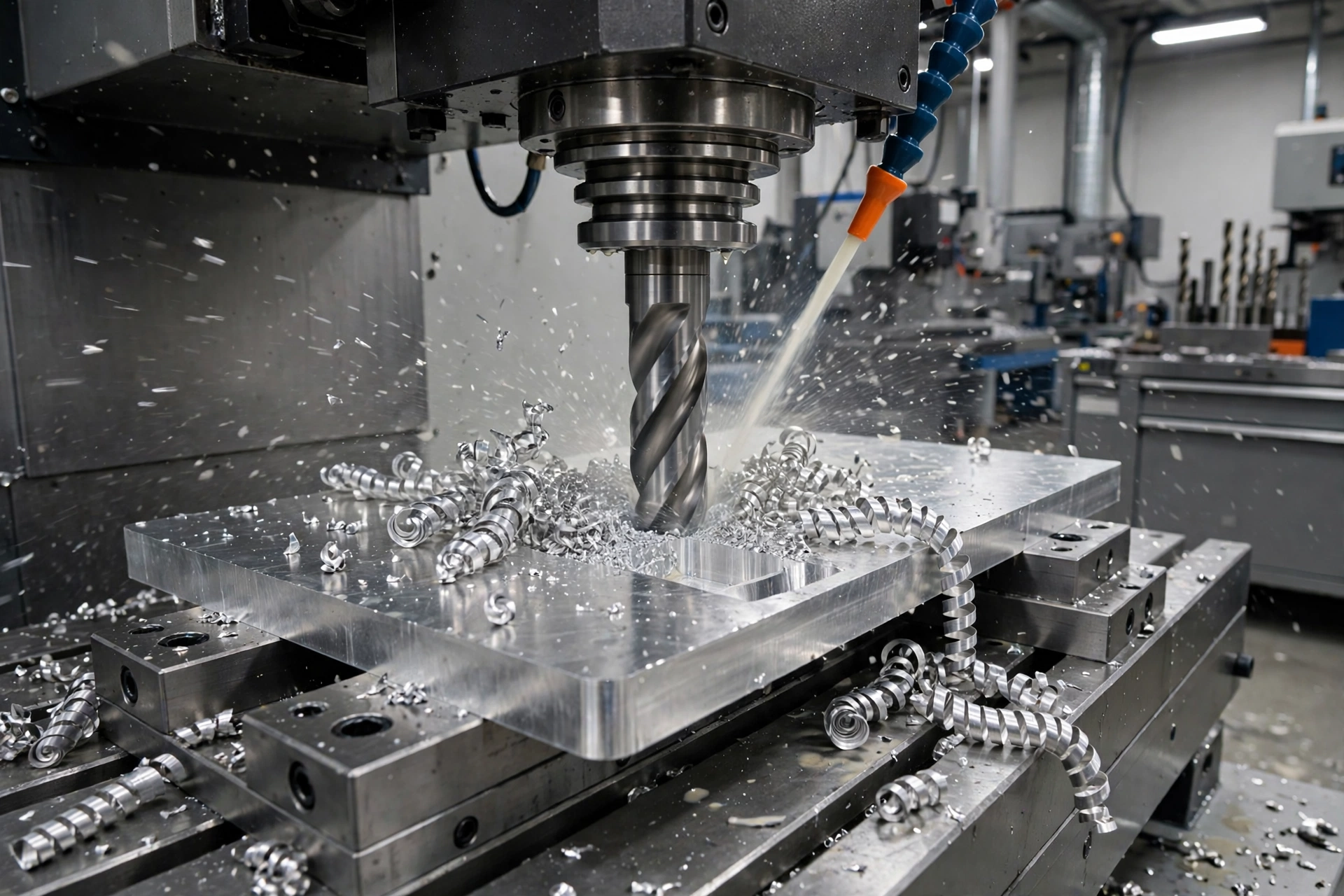
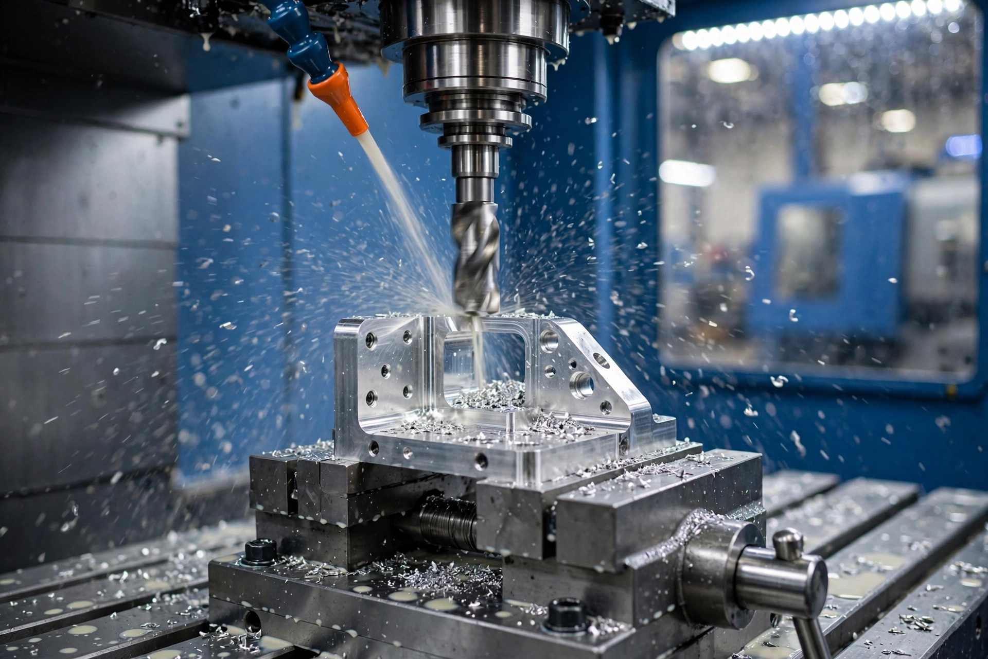
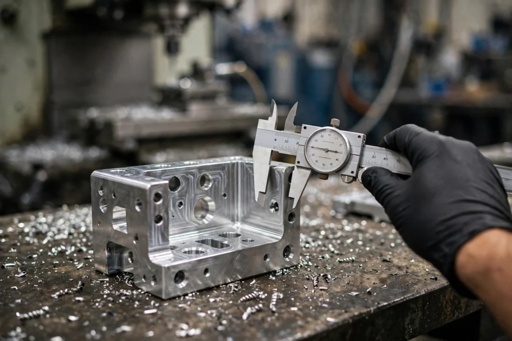
In rapid prototyping, machined prototypes matter when the prototype must behave like the production part. A bracket machined from aluminum tests real strength, thread fit, and surface finish in ways a printed plastic part cannot. For functional testing, tolerance checks, and metal parts, machining is often the right prototype method. Machined parts are usually stronger, with better surface finish, than most printed parts.
Prototyping also de-risks the move to production. A design proven as a machined prototype transfers to production machining with fewer surprises, and the prototype run reveals fixturing and tolerance problems early. Our CNC加工サービス cover both prototype and production work, so the same team carries the design through.
A good prototype program plans the production path from the first loop of the prototyping phase. Materials chosen for prototypes should match production materials where function is tested, and features should be designed so they can be made at volume. For alloy choice, our guide to machining 6061 aluminum covers the alloy most often used for machined prototypes and parts.
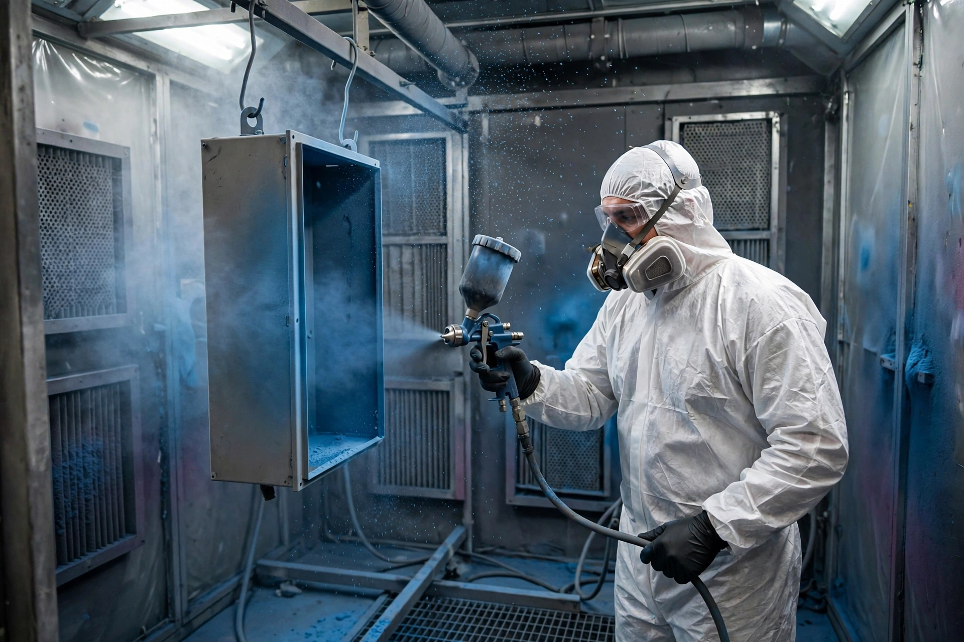
Finishing belongs in the plan too: a prototype that will be coated in production should be tested with its finish. Our powder coating guide explains how coated finishes behave on machined metal, which helps buyers specify prototypes that match the final product.
Tuowei’s published figures for milled aluminum are ±0.005 in (±0.127 mm) for standard features and ±0.001 in (±0.025 mm) for high-precision features such as bearing bores and sealing faces. For parts without their own callout, the ISO 2768-1 general tolerance standard sets four classes; on precision parts, the fine class allows ±0.05 mm on sizes from 0.5 to 6 mm and ±0.1 mm on sizes over 6 to 30 mm.
Material choice changes what those tolerances mean in use. 6061-T6 aluminum has a typical ultimate tensile strength of 45 ksi (310 MPa) and a yield strength of 40 ksi (276 MPa), with a density of 2.70 g/cm³ and thermal conductivity of 167 W/m·K; 7075-T651 reaches 83 ksi (572 MPa) with a Brinell hardness of 150. Our aluminum prototype machining guide covers grade choice, cost, and lead time in more depth.
Machine the prototype when the test needs production material, tight tolerances, or real threads. Printed plastic cannot prove the strength of a metal part, and a printed thread cannot prove how a tapped hole will hold. For those tests, machining is the honest method.
Size also decides the method: Tuowei’s CNC milling handles parts up to 4000 × 1500 × 600 mm, and CNC turning up to 200 × 500 mm. Tuowei’s CNC prototype tolerance runs down to ±0.005 mm depending on material and geometry, so a part larger than a printer’s build volume, or held to a tight tolerance, may need machining or a split design.
In rapid prototyping, prototypes answer the questions they are built to answer, and no further. A printed plastic part cannot prove the strength of a metal production part, and a single prototype cannot prove long term durability. Treating a prototype result as production proof is the most common misuse of the method.
Prototype materials, finishes, and tolerances also differ from production. Printed layers, cast resins, and hand finishing all leave traces that production processes may not. Buyers should ask what a prototype does and does not prove before deciding on its evidence.
The same handful of problems causes most remakes. Sharp internal corners cannot be cut square by a round end mill, so add a radius slightly larger than the tool. Thin walls can chatter during cutting and spring back after unclamping, so thicken them for the first build if function allows.
Tight limits on every dimension raise cost and lead time without improving fit, so put tight limits only on features that mate with something. Anodizing also closes up tight bores and threads, so ask for those features to be masked or machined to allow for the finish.
The cost of rapid prototyping depends on part size and complexity, the method chosen, the material, the quantity, and the finishing and tolerance requirements. A small part from a 3D printer for a shape check costs far less than a machined metal prototype held to tight tolerances, and a batch of cast parts costs more than a single print because of mold work.
Because of those variables, no single price applies to every prototype job. The reliable way to budget is to request a quote for your specific parts, quantities, and requirements, and to compare methods on what each one proves rather than on unit price alone. A cheaper prototype that answers the wrong question is the most expensive option.
Lead time is part of cost. Tuowei publishes prototype shipping in 3 to 7 days, with small batches in 1 to 2 weeks. CNC aluminum prototypes of 1 to 100 pieces typically ship in 1 to 5 business days, and batches of 101 to 10,000 pieces in 5 to 15 business days. CNC prototype lead time starts from 1 day. Quote responses arrive within 12 hours for aluminum prototypes and within 24 hours generally.
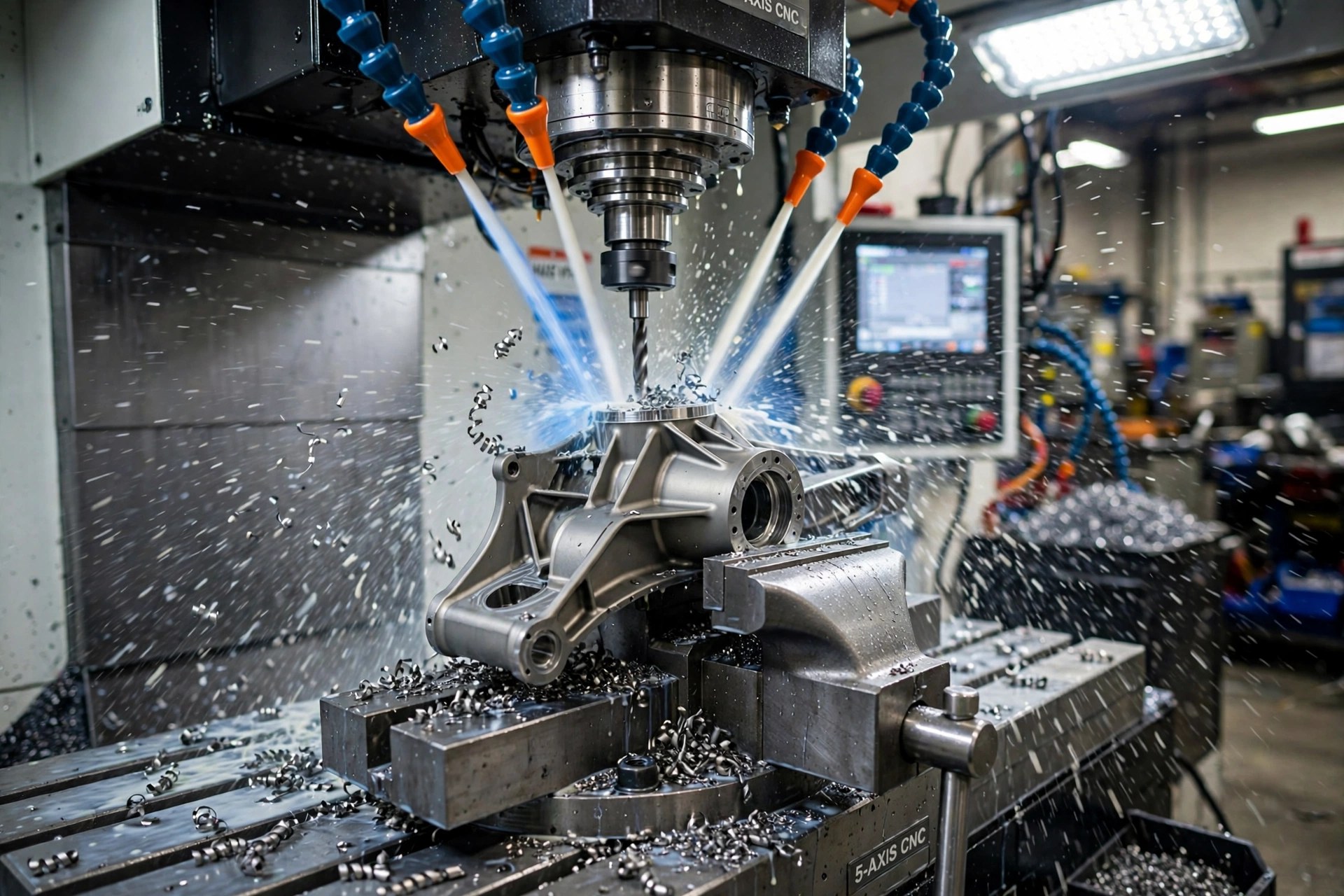
Hourly rates vary by capability. Tuowei’s published 5-axis CNC pricing typically runs $75 to $250 per hour, higher than traditional machining, though fewer setups and less production time often bring total cost down. For complex parts, our 5軸CNC加工サービス page explains when five-axis work earns its rate.
Ordering two or three pieces instead of one often costs only a little more in total, because setup is already paid for. That spare is useful if the first part is damaged in testing, and it gives the team a second sample for a parallel test.
Inspection documents also add cost, and buyers should budget for them. A basic dimensional check is quick, while a CMM report or first article inspection adds engineering time. Decide what evidence the project needs before the build starts.
A good brief prevents the most common delay: missing information. Send a 3D CAD file in STEP or IGES format, a 2D drawing for threads, datums, and any callout tighter than the general note, plus grade and temper, quantity including spares, surface finish and color, and inspection needs. State which features must be masked if the part will be finished.
Ask for a design review before the build starts. Tuowei’s engineers review drawings and provide design feedback to optimize cost and manufacturability, and a review catches thin walls, sharp corners, and impossible tolerances while changes are still free. Tuowei has delivered 250,000+ custom designs to 7,500+ customers over 24+ years, with a 99.8% on-time delivery rate. For the company behind this guide, see 卓偉精密.
It means building a physical model of a part quickly from a three-dimensional design, so the design can be tested and improved before production. The emphasis is on fast learning cycles: build, test, refine, and repeat until the design is ready.
Common examples include an enclosure made using 3D printing and checked for fit, a CNC machined aluminum bracket tested under load, a urethane cast housing used for a small trial batch, and a sheet metal panel formed to verify bend geometry. Each example tests a different property of the design.
No. 3D printing is one family of prototyping approaches, but the field also includes CNC machining, urethane casting, and sheet metal forming. Printing suits fast shape checks, while machining and casting suit functional tests and production-like materials. The ISO/ASTM 52900 standard treats printing as one branch of additive manufacturing rather than the whole field.
The main advantages for product development teams are faster development, earlier fault detection, lower cost of design changes, and better communication with stakeholders. A physical part settles arguments that drawings cannot, and each test round removes risk from the production design.
Prototyping is important because design errors are cheapest to fix early. A prototype reveals fit problems, assembly issues, and performance gaps before tooling is cut, when changes still cost a revised file rather than a revised mold. That early evidence also helps teams commit to production with fewer unknowns.
Start from what the prototype must prove in the design phase. Choose printing for fast shape and fit checks, machining for functional tests in real materials, and casting for small batches of production-like parts. Then weigh speed, accuracy, material, and budget, and ask your supplier what each manufacturing technique can and cannot prove.
Prototyping turns a design file into a part that can be tested, and that test is the whole point. The method matters less than the loop: build fast, test honestly, and refine until the design earns production. Done well, this approach ships products with fewer surprises.
Start with the question the prototype must answer, choose the method that answers it, and plan the path from the first loop to production from the start. A prototype program that follows that order gives production tooling a design already proven in physical form.