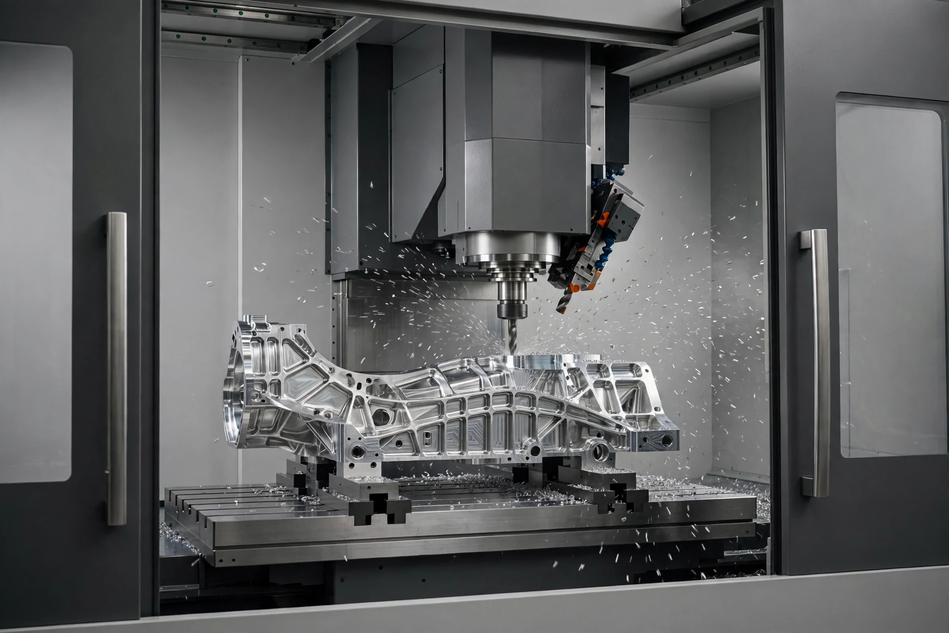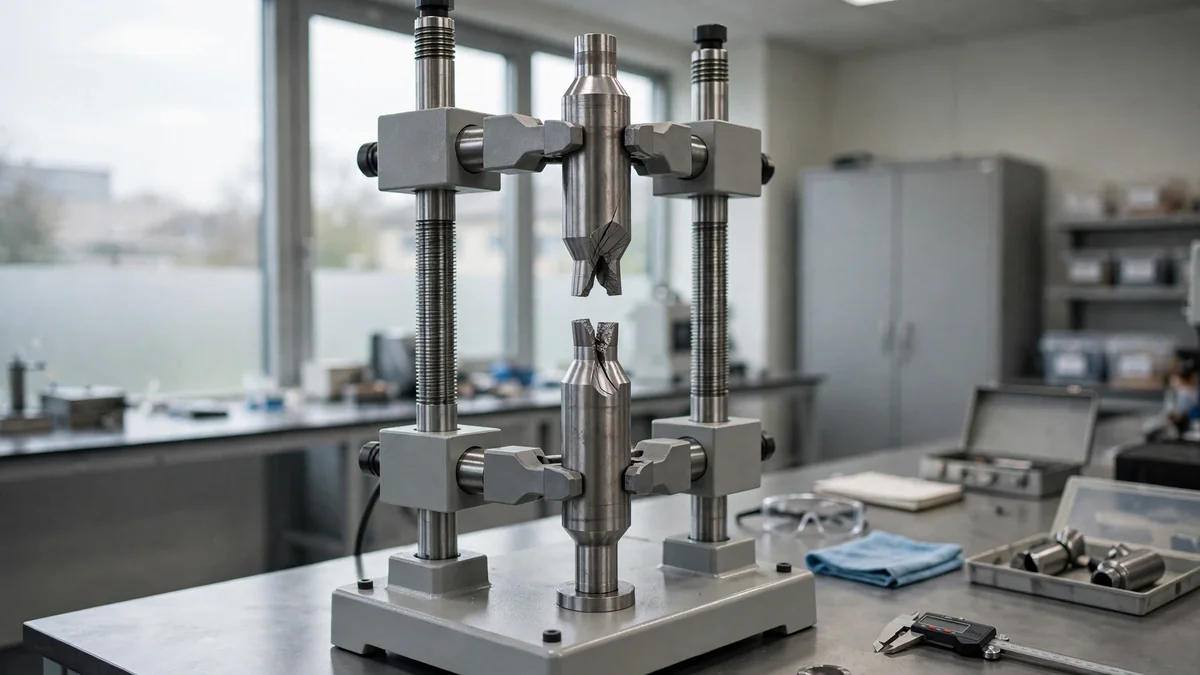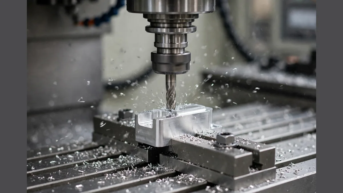
CNC prototype machining turns a CAD model into a real part, in real material, fast enough to test a design before production tooling exists. Unlike 3D printing, the prototype is cut from the same metal or engineering plastic the final part will use, so mechanical tests, thermal tests and fit checks transfer directly to production.
Short answer: A single CNC machined prototype in aluminum costs $80 to $500 for a palm-sized part and ships in 3 to 7 business days. Tolerances of ±0.05 mm are standard; ±0.01 mm is achievable on critical features. The design rules that save the most money are using standard tool radii in internal corners, limiting the number of setups and specifying tight tolerances only where they matter.
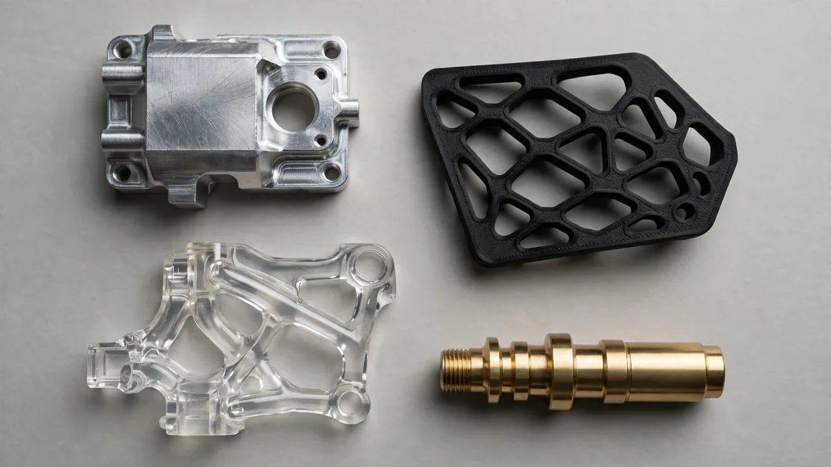
CNC (computer numerical control) machining is a subtractive process. A rotating cutter removes material from a solid block following a programmed toolpath. For prototyping, the block is usually aluminum, steel, brass or an engineering plastic like Delrin, polycarbonate or PEEK.
CNC prototype machining is the right choice when any of these apply:
The part must be tested in the production material, not a printed approximation.
Tolerances tighter than ±0.1 mm are required for fit or function.
The prototype will face mechanical loads, vibration, pressure or temperature in testing.
Surface finish must meet a sealing, cosmetic or coating specification.
Quantities of 1 to 20 parts are needed without tooling investment.
For complex organic shapes, internal lattices or geometry that cannot be reached by a rotating cutter, additive manufacturing may be a better starting point. For simple visual checks where material properties do not matter, 3D printing is faster and cheaper. CNC prototype machining sits where accuracy, material integrity and mechanical performance intersect.
Prototype manufacturing cost for CNC parts is driven by four factors: material, machine time, number of setups and finishing. Here are realistic ranges for a single prototype CNC part approximately 100 mm by 80 mm by 30 mm:
| Matériau | Typical cost (1 pc) | Main cost driver | Notes |
|---|---|---|---|
| aluminium 6061-T6 | $80 to $300 | Machine time, setups | Most common prototype material |
| Aluminium 7075-T6 | $100 to $400 | Material premium, tool wear | Higher strength, needs coating |
| acier inoxydable 304 | $150 to $600 | Slower cutting, tool wear | Harder material, longer cycle |
| Mild steel (1018, A36) | $100 to $400 | Temps machine | Easy to machine, lower material cost |
| Brass (C360) | $120 to $350 | Material cost | Excellent machinability |
| Delrin / POM | $60 to $250 | Temps machine | Fast to cut, good dimensional stability |
| Polycarbonate | $70 to $300 | Chip control, finish | Transparent grades need care |
| PEEK | $200 to $800 | Material cost ($100+/kg) | High performance, expensive stock |
At quantities of 5 to 10 parts, the per-unit cost drops 20 to 40 percent because setup and programming are amortized. At 50 or more, consider whether a different process (die casting, injection molding, or stamping) becomes cheaper per part.
The fastest way to lower a CNC prototype quote is to reduce the number of setups. A part that machines from two sides costs roughly half as much in setup time as one that needs four orientations. Designing for fewer setups is the single most effective cost lever on prototype CNC parts.
CNC machining tolerances depend on the material, the feature type and the machine. The table below shows achievable tolerances for prototype work, assuming a well-maintained 3-axis or 5-axis CNC mill with standard tooling.
| Matériau | Tolérance standard | Tight tolerance | Notes |
|---|---|---|---|
| Aluminium (6061, 7075) | ±0,05 mm | ±0,01 mm | Machines en bon état, stables |
| Stainless steel (304, 316) | ±0,05 mm | ±0,02 mm | Work hardening affects finish |
| Acier doux | ±0,05 mm | ±0,02 mm | Straightforward to hold |
| Laiton | ±0,05 mm | ±0,01 mm | Excellent dimensional stability |
| Delrin / POM | ±0,05 mm | ±0,02 mm | Slight thermal expansion |
| Polycarbonate | ±0,1 mm | ±0,05 mm | Flexible, stress cracks at cuts |
| PEEK | ±0,05 mm | ±0,02 mm | Machines like metal |
For most prototype CNC parts, a general tolerance class such as ISO 2768-m (medium) covers non-critical dimensions. Call out tight tolerances only on mating faces, bore fits and features that must align with other parts. Every tight callout adds inspection time, which adds cost.
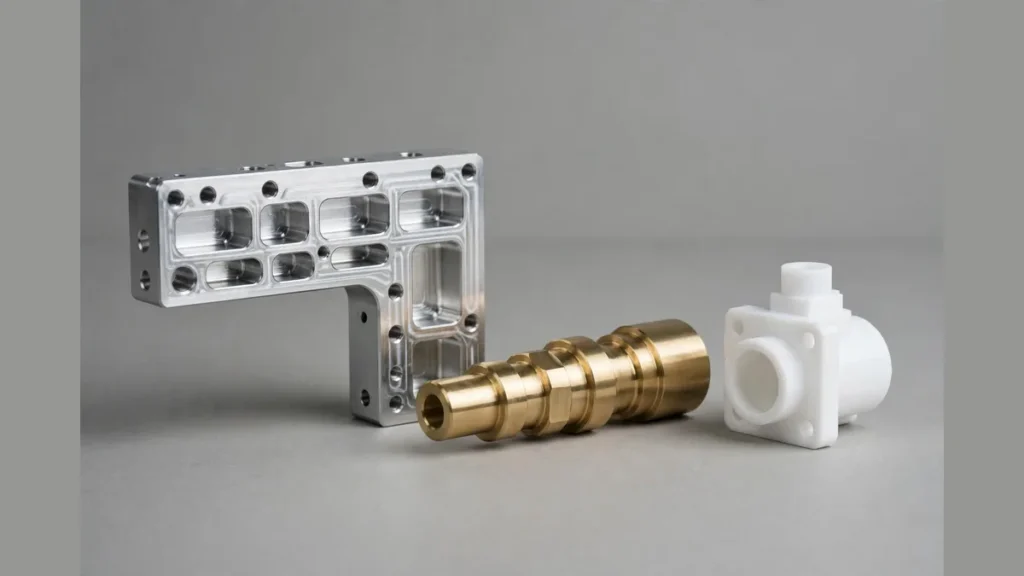
The design decisions that have the biggest effect on CNC prototype machining cost and lead time are geometry choices that determine how many setups the part needs, how long the tool must be and how slowly it must cut.
Internal corner radii. An end mill always leaves a radius in an internal corner. If your design requires a 1 mm radius, the shop needs a 2 mm diameter cutter, which is fragile and slow. A 3 mm radius allows a 6 mm cutter that runs three to four times faster.
Use the largest radius the design can tolerate, and use standard tool sizes: 3 mm, 4 mm, 5 mm, 6 mm, 8 mm, 10 mm radius.
Minimum wall thickness. For aluminum, walls down to 0.5 mm are possible on short, well-supported features. For steel, 0.8 mm is a practical minimum. Taller unsupported walls need more thickness to avoid chatter and deflection. A 1 mm wall 5 mm tall machines easily; the same wall at 40 mm tall is a problem. When in doubt, add ribs instead of thickness.
Hole depth. Standard twist drills reach about 5 times diameter without special measures. Deeper holes need peck drilling or gun drilling, both of which are slower and more expensive. Keep blind holes to 4 times diameter where possible.
Pocket depth. Deep, narrow pockets force the shop to use long, thin cutters that deflect and chatter. Keep pocket depth below 4 times the smallest corner radius. If a deep pocket is unavoidable, step the pocket wider as it goes deeper so the shop can use a stiffer tool.
Thread size. Standard thread sizes (M3, M4, M5, M6, M8 metric or #4-40, #6-32, 1/4-20 imperial) use stock taps that every shop has. Non-standard threads need thread milling or a special tap, both of which add cost and lead time.
Number of setups. Each time the part must be reoriented in the fixture, the shop spends time on setup, alignment and first-piece verification. A part that machines from two sides is significantly cheaper than one that requires four or five orientations. Design features on as few faces as possible, or move to Usinage CNC à 5 axes where tilting the tool or part can reach multiple faces in one clamping.
The finish on a prototype serves two purposes: cosmetic appearance and functional performance. CNC machining leaves tool marks that range from barely visible (Ra 0.8 microns with a fine finish pass) to clearly textured (Ra 3.2 microns from a standard pass). Post-machining finishing changes both the look and the properties.
| Terminer | Utilisation courante | Roughness range | Added cost | Lead time impact |
|---|---|---|---|---|
| Tel qu'usiné | Functional parts, hidden surfaces | Ra 1.6 to 3.2 um | Aucun | Aucun |
| Grenaillage de billes | Even matte appearance | Ra 2 to 4 um | Faible | +0.5 to 1 day |
| Type II anodize | Color, corrosion protection (aluminum) | Variable | Moyen | +1 to 2 days |
| Revêtement dur de type III | Wear resistance (aluminum) | Variable | Plus élevé | +1 to 3 days |
| Conversion au chromate | Corrosion, conductivity (aluminum) | Pas de changement | Faible | +1 day |
| Peinture en poudre | Color, protection (any metal) | Textured | Moyen | +1 to 2 days |
| Polissage | Mirror finish, optical | Ra < 0.4 um | High (manual) | +2 to 5 days |
| Oxyde noir | Mild protection, appearance (steel) | Pas de changement | Faible | +1 day |
If the production part will be anodized, anodize the prototype too. The coating adds 5 to 25 microns per side, which affects bore fits, threads and mating faces. Discovering that after the production mold is cut is an expensive lesson. Our Services d'usinage CNC include in-house anodizing, bead blasting, powder coating and chromate conversion so the prototype ships finished, not raw.
A prototype that has not been measured is an assumption, not a test. Good prototype shops include dimensional inspection as part of the job, but the depth of that inspection varies.
Standard dimensional check. Critical dimensions are measured with calipers, micrometers or gauge pins and recorded on an inspection sheet. This is included in most prototype quotes.
CMM (coordinate measuring machine) report. A CMM touches dozens to hundreds of points on the part and generates a report comparing actual dimensions to the drawing. This is standard for tight-tolerance prototype CNC parts and for first article inspection in regulated industries.
First article inspection (FAI). For composants aérospatiaux, a formal FAI per AS9102 documents every dimension, material certification and process record on the first production part or prototype. This is significantly more work than a standard check and should be specified on the purchase order if required.
Material certification. A mill test report (MTR) or material certificate traces the alloy, temper and heat lot of the stock used. If the prototype test results will be used to qualify the design, traceability matters.
Ask for the level of inspection your project needs at quoting time, because adding a full CMM report after the parts ship means re-fixturing and re-measuring, which costs almost as much as the original inspection.
The file you send determines how quickly and accurately a shop can quote and machine your prototype. These are the formats that matter:
STEP (.stp, .step) is the preferred format for CNC prototype machining. It carries full 3D solid geometry that every CAM system can import. STEP AP214 is the most widely supported variant.
IGES (.igs, .iges) is an older format that works but carries surface data rather than solid data. Some shops need to stitch surfaces into a solid, which can introduce errors if the model is not watertight.
Native CAD files (SolidWorks .sldprt, Inventor .ipt, Fusion 360 .f3d, Creo .prt) are accepted by shops that run the same software. Send a STEP alongside the native file as a backup.
2D drawing (PDF) is essential even when the shop machines from the 3D model. The drawing captures tolerances, surface finish callouts, thread specifications, material and temper, and any notes about critical features that the 3D model cannot convey. A missing drawing is the most common cause of quoting delays and manufacturing surprises.
STL and 3MF files are mesh formats built for 3D printing. They lose the precise surface geometry that CNC toolpaths need, so they are not suitable for machining. If you only have an STL, the shop will need to reverse-engineer a solid model from it, which adds time and cost.
CNC prototype machining has no minimum order quantity. One part is a valid order. That said, the per-unit cost drops as quantity rises because setup and programming are shared across more parts.
| Quantité | CNC per-unit cost trend | Consider switching to |
|---|---|---|
| 1 to 5 | Highest per unit (setup dominates) | Nothing; CNC is ideal here |
| 5 to 20 | 20 to 40% lower per unit | Still CNC for metals |
| 20 to 100 | Diminishing returns | Vacuum casting (plastics), rapid tooling |
| 100 à 1 000 | Flattening curve | Prototype injection molding, die casting |
| 1,000+ | Machine time dominates | Production injection molding or die casting |
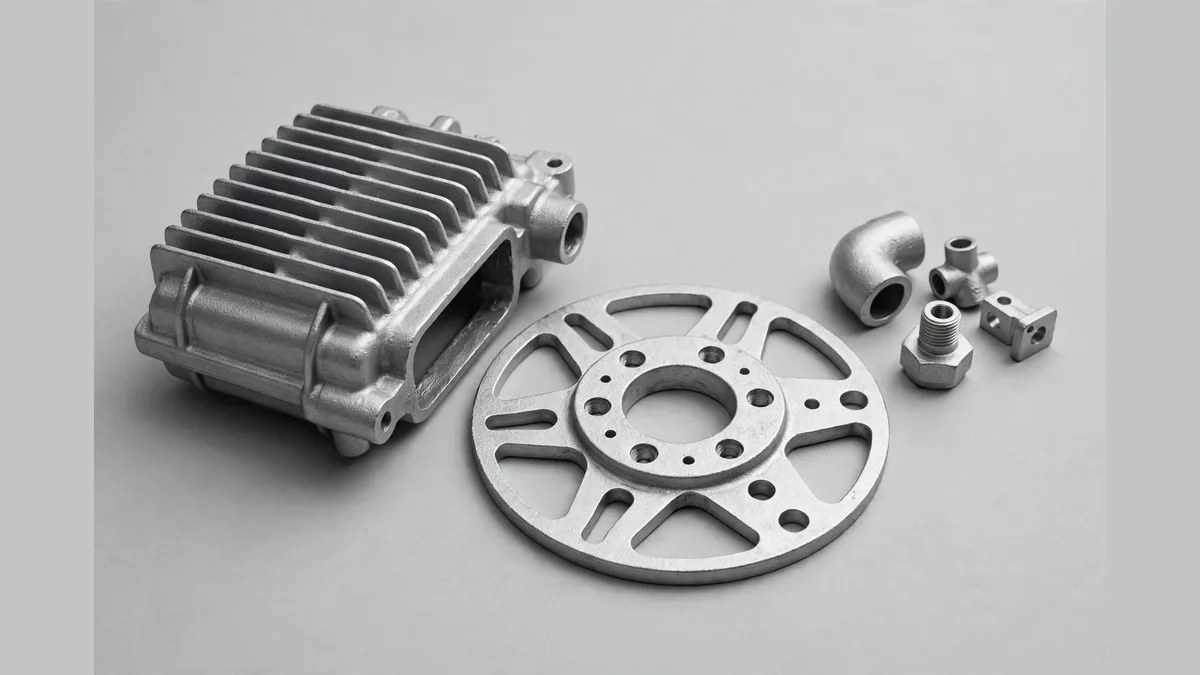
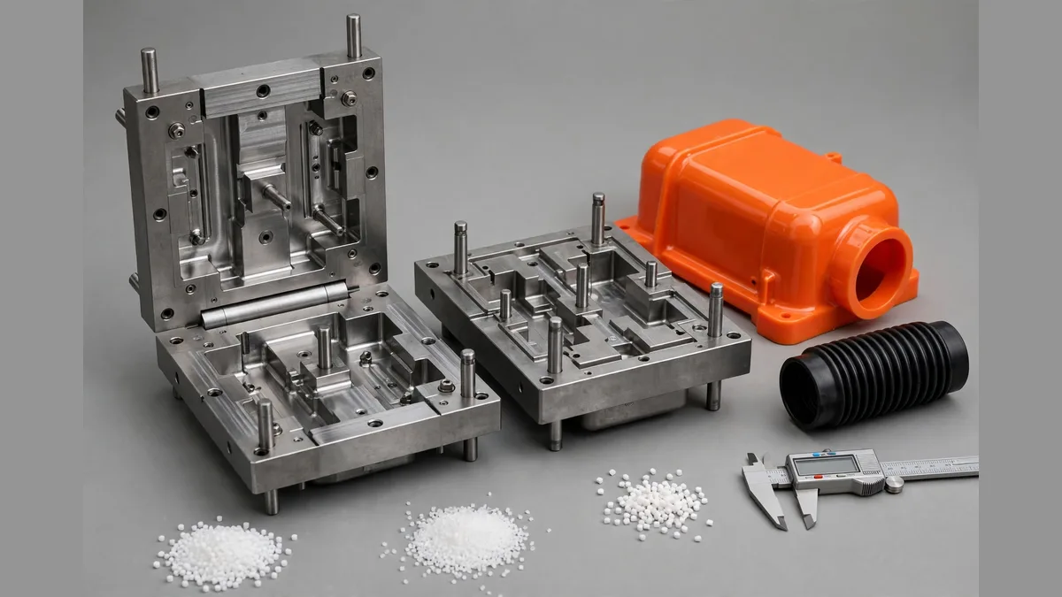
The break-even point between CNC and injection molding depends on part complexity, but for a typical plastic housing it sits around 100 to 500 parts. For metal parts, the break-even with die casting is usually higher, around 500 to 2,000 parts, because die casting tooling costs more than a plastic injection mold.
The best prototype programs plan for production from the start. That means choosing a prototype material that matches the production intent, holding tolerances the production process can replicate, and designing geometry that works in both CNC and the eventual production method.
Au Précision Tuowei, CNC prototyping and production machining run on the same equipment. The setup sheets, fixture designs and inspection data from the prototype carry forward into production, which eliminates the ramp-up time that comes from handing a proven design to a new shop.
For production volumes that justify a switch from machining to casting or molding, keeping the prototype and production supplier in one place means the engineer who machined the prototype can review the casting or mold design for manufacturability. That review often catches issues that would otherwise surface as first-article failures. Our Services de fraisage CNC et usinage de précision teams handle both prototype and production runs in aluminum, steel, brass and engineering plastics.
For a palm-sized aluminum part, expect $80 to $300 for a single piece. Steel prototypes run $150 to $600. PEEK and other high-performance plastics can reach $200 to $800. Complexity, number of setups and surface finishing drive the final number.
Standard CNC machining tolerances are ±0.05 mm on most materials. Tight tolerances of ±0.01 mm are achievable on aluminum and brass for critical features. Use a general tolerance class like ISO 2768-m for non-critical dimensions and call out tight limits only where function demands it.
Standard lead time is 3 to 7 business days from order confirmation. Rush services can deliver in 1 to 2 days at a premium. Lead time assumes a clean STEP file and 2D drawing with no design issues requiring clarification.
Send a STEP (.stp) file for the 3D model and a PDF drawing with tolerances, material, finish and critical dimension callouts. STEP AP214 is the most widely compatible format. STL files are not suitable for CNC machining because they lose the precise surface data the toolpath requires.
For plastic parts, the crossover typically falls between 100 and 500 pieces, depending on part complexity and mold cost. For metal parts switching to die casting, the break-even is usually 500 to 2,000 pieces. Request quotes for both methods at your target volume to see the real crossover point.