
- What Is CNC Milling? A Working Definition
- How Does CNC Milling Work? From CAD Model to Finished Part
- Machine Parts: What Each Component Does
- Types of CNC Milling Machines: Vertical, Horizontal and Multi-Axis
- Types of Milling Operations
- Climb Milling vs Conventional Milling
- What Is a CNC Milling Machine Used For?
- Which Materials Machine Well on a Mill?
- How Accurate Is CNC Milling? Tolerances and Surface Finish
- Designing Parts for CNC Milling
- Where Milled Parts Commonly Go Wrong
- Milling vs CNC Turning or 3D Printing: Which Fits the Part?
- Advantages of CNC Milling and Its Limitations
- Questions fréquemment posées
- Getting a Part Milled: What to Send Your Machine Shop
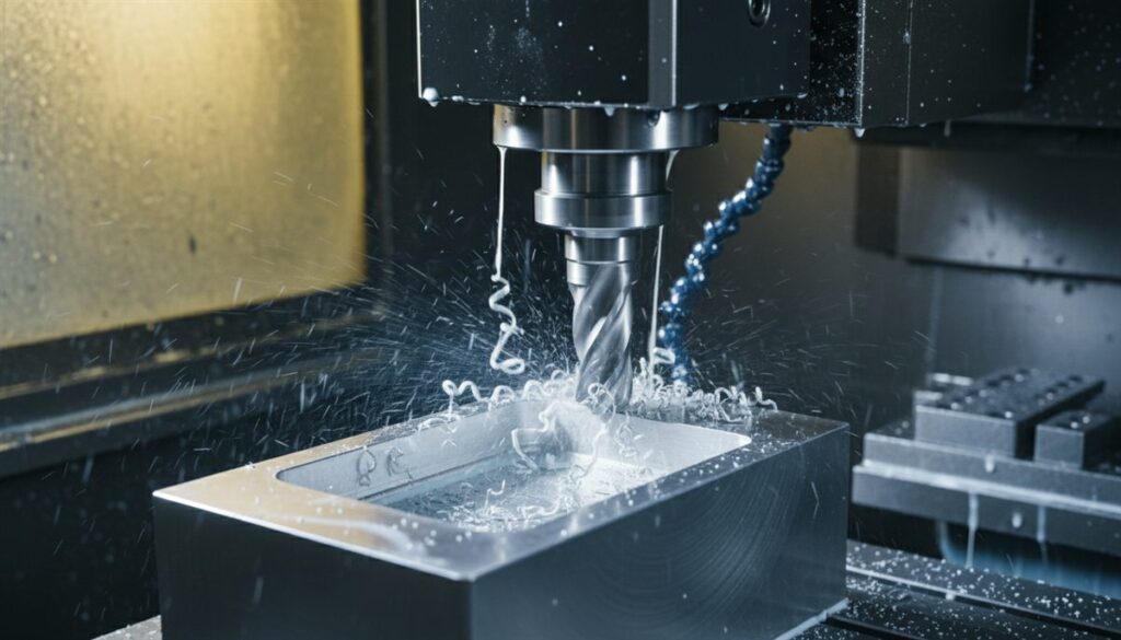
CNC milling makes a large share of the custom metal and plastic parts that engineers order: brackets, housings, manifolds, fixtures and prototypes. If you have been asking what is CNC milling and when it is the right process, this guide covers the full picture, from how the machine reads a file to the tolerances you can realistically expect.
Réponse courte : CNC milling is a subtractive manufacturing process in which a computer-controlled machine spins a multi-point cutting tool and moves it through a solid block of material, removing chips until the programmed shape remains. It produces flat faces, pockets, slots, holes and 3D contours in metals and plastics, from one prototype to thousands of parts.
What Is CNC Milling? A Working Definition #
CNC stands for computer numerical control: the machine follows coordinates and commands from a program instead of hand wheels turned by an operator. Milling is the cutting method. A rotating milling cutter with several cutting edges, usually an end mill, takes small chips from a stationary or slowly moving workpiece.
Unlike manual milling, a CNC machine repeats the same toolpath on every part, so the hundredth part matches the first. Modern CNC machines also change tools, switch coolant on and off and probe the part without stopping.
That is the key difference from turning. On a lathe the part spins and the cutting tool stays mostly still. On a CNC mill the tool spins and the part, the tool or both move along the machine axes.
The axes follow a standard Cartesian coordinate system. Under ISO 841, the Z axis runs parallel to the spindle, X and Y form the plane at right angles to it, and the rotary axes A, B and C turn about X, Y and Z. Every CNC mill, from a small 3-axis vertical mill to a 5-axis machining center, describes its motion this way.
For the wider family of processes, including turning, drilling and EDM, see our guide to what CNC machining is and how it works.
How Does CNC Milling Work? From CAD Model to Finished Part #
In a real shop, every part follows the same CNC milling process, and the process begins in software:
- Design the part in CAD. Computer-aided design software produces the 3D model and, ideally, a drawing with tolerances, threads and finish notes.
- Program toolpaths in CAM. Computer-aided manufacturing software turns the model into toolpaths, the exact lines each tool will follow, and sets speeds and feeds for each cut.
- Post-process to G-code. A post-processor translates the toolpaths into G-code, the word-address program format described in ISO 6983-1, tailored to the specific machine’s controller.
- Set up the machine. Depending on the machine, the machinist clamps the raw material (the stock) in a vise or fixture, loads the tools and measures offsets.
- Rough the part. Larger tools remove most of the material quickly, leaving an even allowance on every surface.
- Finish the part. Smaller or sharper tools take light passes to reach final size and surface finish.
- Deburr and inspect. Sharp edges are broken, and critical dimensions are checked against the drawing before the part ships or goes on to finishing.
Setup is where much of the real skill sits. The machinist sets a work offset, the part’s zero point inside the machine, usually by touching a probe to a datum face. Each tool gets a length offset so the controller knows where its tip is. A wrong offset is a common reason a first part comes out the wrong size, which is why shops measure a first article before running the batch.
Machine Parts: What Each Component Does #
A CNC machine is a machine tool with motors, a controller and a spindle in place of hand wheels. Here is the basic anatomy of a CNC mill, which helps when you read a shop’s equipment list:
| Composant | What it does |
|---|---|
| Spindle | Holds and rotates the cutting tool. Its speed, power and torque limit which materials the milling machine handles well. |
| Tool holder and collet | Clamp the cutting tool in the spindle. Runout here shows up in finish and tool life. |
| Axes, ball screws and servo motors | Milling machines move the table, head or column along X, Y and Z. Ball screws turn motor rotation into linear motion with high precision. |
| Worktable or bed | Supports the vise, fixture or part. Table size sets the largest part the machine accepts. |
| Automatic tool changer | Swaps tools from a magazine in seconds, so one program can face, drill, tap and contour without stopping. |
| Controller | Reads the G-code, drives the motors and manages offsets, coolant and the tool changer. It enables the machine to run without an operator at the hand wheels, which is how CNC machines operate. |
| Coolant system | Removes heat and flushes chips away from the cut. |
Types of CNC Milling Machines: Vertical, Horizontal and Multi-Axis #
Types of milling machines are grouped by spindle orientation and by how many axes move at once. Vertical and horizontal milling machines cover most shop work; the table lists the various types you will meet.
| Type of CNC mill | Comment ça marche ? | Idéal pour |
|---|---|---|
| Vertical milling machine (VMC) | Spindle points down. The most common machine shop setup. | Plates, brackets, housings, prototypes |
| Horizontal machining center (HMC) | Spindle lies flat, so chips fall away. Often has pallet changers. | Production runs and parts machined on several sides |
| 3-axis milling | 3-axis milling machines move the tool in X, Y and Z. Each face is cut in a separate setup. | Prismatic parts with features on one or two sides |
| 4-axis milling machine | Adds a rotary A axis, so the part can be indexed or turned during the cut. | Features around a cylinder, multi-side parts with fewer setups |
| 5-axis milling machines | Two rotary axes tilt the tool or part. Can run as 3+2 positioning or full simultaneous motion. | Impellers, aerospace brackets, deep or angled features |
| Gantry or bridge mill | Large CNC machines where the spindle travels on a bridge over a fixed table. | Large plates, molds and frames |
| Fraiseuse à commande numérique | Lighter frame, high-speed spindle, large flat bed. | Wood, plastics, composites and aluminum sheet |
A vertical milling machine with three axes does most everyday CNC milling. Our position: design a first prototype for 3-axis where possible, and move to Usinage CNC à 5 axes when the part needs undercuts, compound angles or four or more setups. Five-axis time costs more per hour, but on the right part it removes setups and the errors that stack up between them.
Types of Milling Operations #
CNC milling operations are usually combined in one program, each matched to a feature and to a different cutting tool. Milling is often paired with drilling and tapping on the same machine.
| Operation | What it makes |
|---|---|
| Face milling | Flat, square top surfaces, usually the first cut on raw stock |
| Plain (slab) milling | Wide flat surfaces cut with the side of a cylindrical cutter |
| End milling and pocketing | Pockets, steps and outside profiles |
| Slotting | Keyways and narrow channels |
| Angular milling | Chamfers, dovetails and angled faces |
| Form and 3D contour milling | Curved surfaces, fillets and mold shapes, often with ball-nose cutters |
| Drilling, tapping, boring and thread milling | Holes, threaded holes and precise bores, done on the same machine |
Climb Milling vs Conventional Milling #
Cutting direction is rarely covered in beginner guides, yet it changes finish and tool life on every pass. It describes how the cutter’s rotation meets the feed direction.
- Climb milling: the tooth enters the material at full chip thickness and exits thin. The chip carries heat away, the edge rubs less, and the finish is usually better. It is the default on modern CNC machines.
- Conventional milling: the tooth enters thin and exits thick. It rubs before it bites, which raises heat and can work-harden stainless steel and titanium.
There is an exception. Climb milling pulls the cutter into the work, so it needs a rigid CNC machine with no ball screw backlash. Conventional milling is still safer on worn machines, on castings with hard scale, and sometimes on a flexible wall.
What Is a CNC Milling Machine Used For? #
A milling machine suits any part that is mostly prismatic, meaning built from flat faces, pockets and holes. On 5-axis machines, CNC milling can produce complex geometry such as impellers too. Typical uses:
- Aérospatiale : brackets, ribs and manifolds in aluminum and titanium.
- Dispositifs médicaux : instrument parts and implant prototypes in stainless steel, titanium and PEEK.
- Automobile : prototypes, test fixtures and low-volume parts.
- Électronique : enclosures, heat sinks and RF housings.
- Industrial equipment: jigs, fixtures, pump housings and machine parts.
A CNC milling machine used for prototyping needs no tooling: a design change only means editing the CAD model and regenerating the program.
Which Materials Machine Well on a Mill? #
Almost any rigid material can be milled. These are the ones Tuowei mills most often for custom parts:
| Material group | Common grades | Machining notes |
|---|---|---|
| Aluminium | 6061, 7075, 5052 | Fast to cut, good finish, lowest cost per part |
| Steel and stainless steel | 1018, 4140, 304, 316 | Slower speeds; stainless work-hardens if the tool rubs |
| Titane | Grade 2, Grade 5 (Ti-6Al-4V) | Low heat conductivity, needs rigid setups and sharp tools |
| Laiton et cuivre | C360, C260, C101, C110 | C360 brass is among the easiest metals to machine |
| Plastiques | POM (Delrin), PEEK, ABS, nylon, polycarbonate, acrylic | Sharp tools and heat control to avoid melting and burrs |
Higher hardness means slower cutting and faster tool wear. It is possible to machine composite materials and ceramics too, but they need specialized tools and dust control.
How Accurate Is CNC Milling? Tolerances and Surface Finish #
An engineering tolerance is the allowed variation on a dimension. When a drawing gives no specific tolerance, most shops apply a general standard. ISO 2768-1 is the one most drawings reference:
| Nominal size | Fine (f) | Medium (m) |
|---|---|---|
| 0.5 to 3 mm | ±0.05 mm | ±0.1 mm |
| Over 3 to 6 mm | ±0.05 mm | ±0.1 mm |
| Over 6 to 30 mm | ±0.1 mm | ±0.2 mm |
| Over 30 to 120 mm | ±0.15 mm | ±0.3 mm |
| Over 120 to 400 mm | ±0.2 mm | ±0.5 mm |
Tighter limits are possible on specific features. Tuowei quotes ±0.005 in (±0.127 mm) as its standard CNC milling tolerance and ±0.001 in (±0.025 mm) for high-precision features. It depends on part size, material, wall thickness and inspection method, so verify the figure on the quote for your part.
Our position: use ISO 2768-m as the default and call out tight tolerances only where a feature needs them, because each one adds machining and inspection time. For alloy-specific numbers, see our notes on realistic tolerances for aluminum parts.
Surface roughness is measured as Ra, the average height of the surface’s peaks and valleys. Tuowei as-machined finish is Ra 3.2 µm (126 µin), with visible tool marks. A smooth-machining finish pass brings it to Ra 1.6 µm (63 µin).
Designing Parts for CNC Milling #
A few design choices decide most of the cost and lead time, because CNC milling allows almost any shape a rotating tool can reach. Tuowei current CNC machining design guidelines:
| Fonctionnalité | Lignes directrices | Pourquoi |
|---|---|---|
| Internal corners | Add a radius, the larger the better | An end mill is round, so a sharp internal vertical corner cannot be cut |
| Epaisseur de la paroi | 0.8 mm (0.031 in) minimum for metals | A thinner section deflects and chatters |
| Hole depth | Up to 4× the tool diameter | Long tools bend and lose accuracy |
| Threads | 2 to 5× diameter depth | Deeper threads add time without adding much strength |
| Engraved text | 0.5 mm minimum line width | Smaller cutters break easily |
Undercuts need special T-slot or dovetail cutters, or a 5-axis machine, so avoid them unless the function requires one.
Where Milled Parts Commonly Go Wrong #
Most rejected milled parts fail for a handful of predictable reasons:
- Chatter: a self-excited vibration between tool and part that leaves a wavy surface. A long, thin tool or a tall, thin wall is the usual cause.
- Tool deflection: the cutting force pushes a slender tool or wall aside, so a wall measures thicker at the top than the bottom.
- Stress warping: plate stock carries internal stress from manufacturing. Removing material unevenly releases it, and the part bows after unclamping even though it measured correctly on the machine.
- Burrs and sharp edges: left on hole exits and slot edges if the drawing does not call for deburring.
A shop prevents most of these with the shortest tool that reaches, light finishing passes, balanced material removal and stress-relieved stock. Speed matters too: a three-flute cutter at 12,000 RPM strikes the wall 600 times per second, and if that sits near the wall’s natural frequency, chatter builds fast. Our guide on how to prevent warping and chatter in thin walls covers the physics in detail.
Milling vs CNC Turning or 3D Printing: Which Fits the Part? #
| Processus | Best geometry | Trade-off |
|---|---|---|
| Fraisage CNC | Prismatic parts, pockets, flat faces, 3D contours | Material waste; internal corners need radii |
| Tournage CNC | Round parts: shafts, pins, bushings | Limited to features around a rotation axis |
| Impression 3D | Internal channels, lattices, organic shapes | Lower accuracy and weaker material properties in most processes |
For flat profiles cut from sheet, laser cutting or plasma cutting is usually the cheaper manufacturing process. Many parts combine milling and turning: a shaft is turned on CNC lathes first, then flats and cross holes are milled. If your part is mostly round, Tournage CNC is usually faster and cheaper.
Advantages of CNC Milling and Its Limitations #
Main benefits:
- High precision and repeatability from the first part to the last, which makes it a dependable production process.
- Works in production-grade metals and plastics.
- No tooling cost: using CNC milling, prototypes and design changes are quick.
- Automation: one operator can run several CNC machine cells, which raises efficiency.
- One milling machine handles faces, pockets, holes, threads and contours.
Limitations of CNC milling:
- Much of the stock can end up as chips, which adds cost on expensive alloys.
- Cost per part falls slowly with volume, so molding or casting wins at high quantities.
- Tool access limits geometry: deep narrow pockets, sharp internal corners and enclosed channels are hard or impossible.
Questions fréquemment posées #
What is meant by CNC milling? #
It means milling done under computer numerical control: a program, not an operator’s hands, drives the rotating cutter through the workpiece to cut the programmed shape.
Is CNC machining the same as milling? #
No. The CNC machining process is the broader term. It covers milling, the CNC turning process, drilling, grinding and other work run on different types of CNC machine. Milling is one type of precision CNC machining.
Is CNC like 3D printing? #
Both start from a CAD file but work in opposite ways. Milling removes material from a solid block; 3D printing adds it layer by layer. Milling is usually more accurate, while 3D printing reaches internal features a cutter cannot.
What are the downsides of CNC milling? #
The main downsides are material waste, higher cost per part at high volume, and geometry limits from tool access, such as rounded internal corners and difficult undercuts.
How much does CNC milling cost? #
The cost of CNC milling depends on material, machine time, setups, tolerances and quantity. A simple aluminum part costs far less than a 5-axis titanium part with tight tolerances, so the reliable way to compare is a quote from your CAD file and drawing.
What is the difference between a CNC router and a CNC mill? #
CNC routers have a lighter frame, a faster spindle and a large flat bed for wood, plastics and sheet. A CNC mill is a heavier, stiffer machine, so it holds tighter tolerances in steel and titanium.
Getting a Part Milled: What to Send Your Machine Shop #
Now that you know what is CNC milling and where it fits, a good quote comes down to the files you send. Include a STEP model, a PDF drawing with tolerances and thread callouts, the material and temper, the finish and the quantity. Flag the few dimensions that truly matter, so the CNC milling process plan focuses on them.
Tuowei Services de fraisage CNC cover 3-, 4- and 5-axis work in metals and plastics, alongside turning and the rest of its CNC machining services, with a free DFM review on every quote. Prototype lead times start at 1 to 5 business days. To discuss a part, contact Précision Tuowei.


