هل تحتاج إلى حلول تصنيع آلية متخصصة؟ فريقنا في Tuowei Proto موجود هنا لمساعدتك في جميع احتياجات التصنيع الخاصة بك. تواصل معنا اليوم للحصول على عرض أسعار لمشاريعك الجارية أو القادمة!
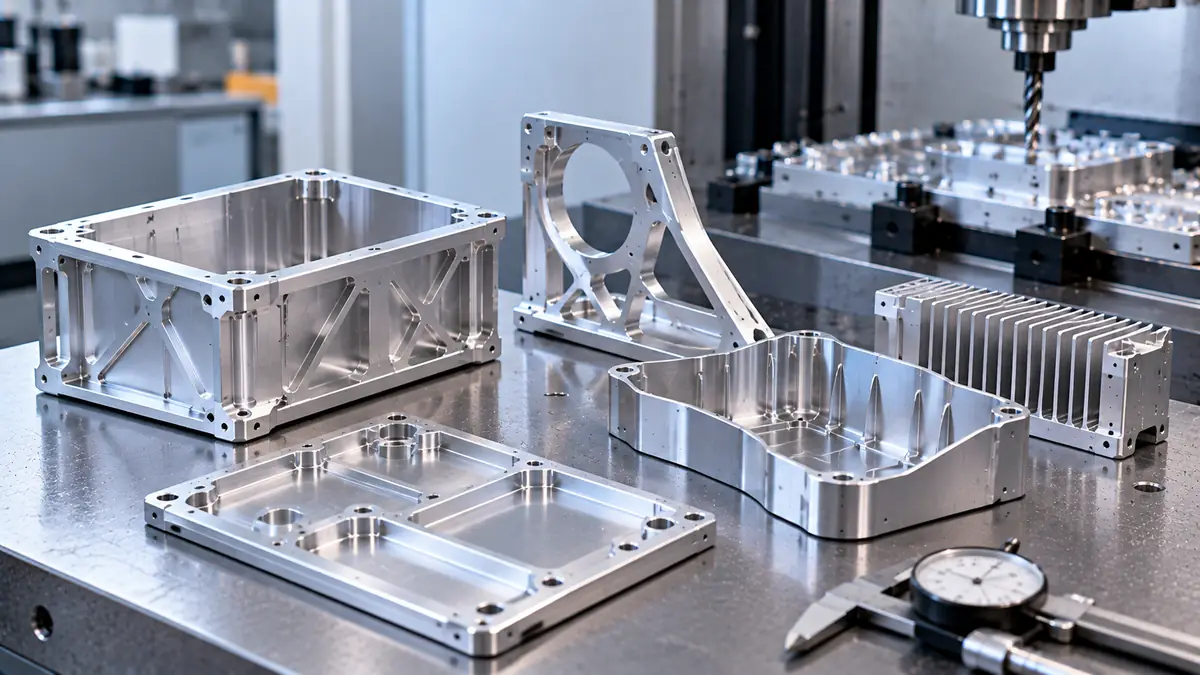
تحدث مشكلتان في عملية تصنيع قطع الألومنيوم ذات الجدران الرقيقة. إما أن تهتز الجدران أثناء القطع، مما يترك علامات اهتزاز وسطحًا متموجًا، أو أن يتحرك الجزء بعد خروجه من الآلة، إما بسبب التحرر غير المتساوي للضغط الداخلي أو بسبب انحناءه بفعل المشابك. ويتم التحكم في كلتا الحالتين بنفس الطريقة: الحفاظ على دعم الجدار لأطول فترة ممكنة، والقطع بقوى خفيفة ومتساوية، والبدء من مادة خام خالية من الإجهاد.
الإجابة المختصرة: لمنع حدوث انحراف، استخدم صفيحة T651 التي خضعت لعملية تخفيف التوتر، وقم بإزالة المادة بشكل متساوٍ من كلا الجانبين، وقم بتشطيب كل الأجزاء بشكل خشن قبل التشطيب النهائي، وقم بتثبيت القطعة دون الضغط عليها بقوة لتسويتها. لمنع الاهتزاز، استخدم أقصر وأحد أدوات القطع التي تصل إلى المكان المطلوب، وقم بعمليات تشطيب شعاعية خفيفة، وقم بتشطيب الجدران العالية على مراحل من الأعلى إلى الأسفل، واضبط سرعة المغزل.
يشرح الجزء المتبقي من هذا الدليل سبب فعالية كل خطوة من تلك الخطوات، مع توضيح المبادئ الفيزيائية الكامنة وراءها، حتى تتمكن من تحديد الخطوات التي يحتاجها جزء معين.
لا يوجد رقم موحد. تصف الأدلة المنشورة الجدار بأنه “رقيق” إذا كان سمكه أقل من 2 ملم، أو أقل من 1.5 ملم، أو إذا تجاوزت نسبة الارتفاع إلى السمك نطاقًا يتراوح بين 10:1 و20:1. ويصبح هذا الاختلاف في الآراء منطقيًّا عندما تدرك أن السمك وحده لا يحدد سلوك الجدار.
ما يهم هو الصلابة، والصلابة تعتمد على كل من الارتفاع والسماكة. فالجدار الذي يرتفع من أرضية جيبية يتصرف تقريبًا كعارضة ناتئة. وعند تعرض حافته الحرة لقوة قص جانبية، يزداد انحرافه مع ارتفاع مكعب ارتفاعه وينخفض مع انخفاض مكعب سماكته.
لذا، فإن الجدار الذي يبلغ سمكه 1 ملم وارتفاعه 5 ملم يمكن تصنيعه بسهولة. أما عند ارتفاع 40 ملم، فإن الجدار نفسه يمثل مشكلة حقيقية. وفي الواقع العملي، يُعتبر الجدار “رقيقًا” عندما تكون قوة القطع كبيرة بما يكفي، مقارنة بصلابته، بحيث تدفعه خارج موضعه أو تجعله يهتز.
ولهذا السبب، يتناول هذا الدليل الجدران الرقيقة المصنوعة من الألومنيوم من حيث الارتفاع والسماكة معًا، بدلاً من تحديد حد أدنى واحد فقط.
هناك خمس آليات تتسبب في معظم المشكلات التي تواجه الأجزاء ذات الجدران الرقيقة. وتظهر هذه الآليات في أوقات مختلفة، وهو ما يُعد أسرع طريقة للتمييز بينها.
| السبب | ما تراه | عندما يظهر | التصحيح الرئيسي |
| انحراف قوة القطع | سمك الجدار في الجزء العلوي أكبر مما كان مخططًا له، ويتناقص تدريجيًا | أثناء القطع؛ القراءات غير صحيحة على الآلة | قم بعمل شقوق شعاعية أخف، ثم قم بالتشطيب على مراحل من الأعلى إلى الأسفل |
| الاهتزاز الذاتي (الاهتزاز الذاتي) | علامات متموجة، تشويش، تشطيب رديء | أثناء القطع | أداة أقصر، سرعة عمود دوران مُعدَّلة، دعم أكبر |
| تحرير الإجهاد المتبقي | تنحني الأجزاء أو تلتوي بعد فك المشبك | بعد إصدار القطعة | مخزون T651، إزالة متوازنة، تشطيب خشن ثم ناعم |
| التشوه الناتج عن التثبيت | ينبثق الجزء من اللوح المسطح بعد فك التثبيت | عندما تنفصل المشابك | بل وحتى قوة تثبيت أقل، أو دعم بالفراغ أو دعم مطابق للشكل |
| الحرارة | يتغير الحجم أثناء القطع، ثم يتغير مرة أخرى أثناء التبريد | أثناء القطع وبعده مباشرة | سائل التبريد، أدوات حادة، إجراء القياس في درجة حرارة ثابتة |
اثنان من هذه العوامل، وهما الإجهاد والتثبيت، لا يظهران إلا بعد تحرير القطعة. فقد تبدو القطعة مثالية على الآلة، ومع ذلك تفشل في الفحص. وهذا هو السبب أيضًا في أن “الالتواء” و“الاهتزاز” يتطلبان حلولًا مختلفة: فالأول مشكلة ثابتة تتعلق بالإجهاد والدعم، أما الثاني فهو مشكلة ديناميكية تتعلق بالاهتزاز.
هناك علاقتان بسيطتان مستمدتان من نظرية العوارض تفسران معظم سلوك الجدران الرقيقة.
الانحراف. بالنسبة لجدار يُعامل على أنه كابولي، فإن الانحراف تحت تأثير القوة نفسها يتناسب مع مكعب الارتفاع مقسومًا على مكعب السماكة. فإذا تضاعف الارتفاع، يزداد الانحراف ثماني مرات. وإذا انخفضت السماكة إلى النصف، يزداد الانحراف أيضًا ثماني مرات.
التردد الطبيعي. التردد الطبيعي الأول للجدار، أي التردد الذي يفضل الجدار أن يهتز به، يتناسب مع السماكة مقسومة على مربع الارتفاع. إذا قُسمت السماكة إلى النصف، ينخفض التردد إلى النصف. وإذا تضاعف الارتفاع، ينخفض التردد إلى الربع.
يستخدم الجدول أدناه معادلة الكابولي لجدار من الألومنيوم 6061، بمعامل مرونة يبلغ 68.9 جيجا باسكال (10.0 × 10³ كيلو باسكال، وفقًا لدليل ناسا 6061) وكثافة تبلغ 2.70 غرام/سم³. تكون الجدران الفعلية المرتبطة بجدران أخرى أو زوايا أكثر صلابة من هذه الحالة المثالية، لذا يجب التعامل مع الأرقام على أنها مقارنة، وليست تنبؤًا.
| سُمك الجدار | ارتفاع الجدار | التردد الطبيعي الأول التقريبي |
| 2 ملم | 20 ملم | 4,080 هرتز |
| 1 ملم | 20 ملم | 2,040 هرتز |
| 2 ملم | 40 ملم | 1,020 هرتز |
| 1 ملم | 40 ملم | 510 هرتز |
والآن قارن ذلك بالمفرزة. تُحسب تردد مرور الأسنان بقسمة سرعة المغزل على عدد الشقوق ثم قسمة الناتج على 60. فالمفرزة الطرفية ذات الشقوق الثلاثة التي تعمل بسرعة دوران تبلغ 12,000 دورة في الدقيقة تصطدم بالجدار 600 مرة في الثانية، أي بمعدل 600 هرتز. ويقع الجدار الطويل الذي يبلغ ارتفاعه 1 مم عند تردد 510 هرتز قريبًا من تردد الإجبار هذا، بينما يقع الجدار القصير الذي يبلغ ارتفاعه 2 مم أعلى منه بكثير.
هذا هو المعنى العملي لمصطلح “رقيق”. فكلما زاد ارتفاع الجدار وأصبح أكثر رقة، انخفض تردده الطبيعي ليقترب من النطاق الذي يعمل فيه القاطع، وتصبح التغيرات الطفيفة في السرعة أو العمق ذات تأثير كبير. وهذا يفسر أيضًا سبب ازدياد صعوبة عملية تفريز الجدران الرقيقة بسرعة كبيرة كلما زاد ارتفاعها.
هناك نقطة أخرى تثير دهشة المصممين: فالتحول من سبيكة 6061 إلى سبيكة 7075 لا يؤدي إلى زيادة صلابة الجدار. تسرد كتيبات ناسا معاملات مرونة تبلغ 10.0 و10.3 × 10³ كيلو سيل، وهما لا يختلفان إلا بنحو 3%. يعتبر 7075 أقوى بكثير، لكن الجدار الذي ينثني في 6061 سينثني بنفس القدر تقريبًا في 7075.
الاهتزاز المتتالي هو اهتزاز ذاتي الإثارة. تترك كل سن سطحًا متموجًا قليلاً. وتصادف السن التالية تلك الموجة، وإذا كان التوقيت غير دقيق، فإن الاهتزاز يزداد مع كل مرور. وفي حالة الأجزاء المصنوعة من الألومنيوم ذات الجدران الرقيقة، قد يكون الجزء المهتز هو الجدار بدلاً من الأداة، ويتغير سلوك الجدار مع انحلال المادة.
يقوم الميكانيكيون بتحديد المناطق التي يكون فيها القطع مستقرًا باستخدام مخطط فصوص الاستقرار، الذي يرسم منحنى يربط بين أقصى عمق قطع خالٍ من الاهتزاز وسرعة المغزل. تقع “الفصوص” المستقرة عند السرعات التي يتطابق فيها تردد مرور الأسنان مع كسر عدد صحيح من التردد الطبيعي للنظام. أظهر باحثو المعهد الوطني للمعايير والتقنية (NIST) أن حدود الاستقرار هذه تتغير أيضًا مع طول الجزء البارز من الأداة، وأن ضبط هذا الجزء البارز يمكن أن يرفع معدل إزالة المواد الخالي من الاهتزاز (شميتز وآخرون، المعهد الوطني للمعايير والتقنية (NIST)).
من الناحية العملية، هذه هي أدوات التأثير:
تختلف التوصيات المتعلقة بسرعة المغزل باختلاف الماكينة وحامل الأداة والأداة نفسها. فالسرعة التي تعمل بشكل جيد على إحدى الماكينات قد تتسبب في اهتزازات على ماكينة أخرى. ويُعد «اختبار النقر» — الذي يقيس استجابة الأداة الترددية باستخدام مطرقة مزودة بأجهزة قياس — المقياس الحقيقي لمستوى الاستقرار في إعداد معين.
يتم تبريد صفيحة الألمنيوم المدرفلة سريعًا بعد المعالجة الحرارية بالمحلول، ويؤدي التبريد السريع إلى تثبيت الإجهادات بداخلها: إجهاد ضغط بالقرب من الأسطح، وإجهاد شد في الوسط. وطالما أن الصفيحة سليمة، فإن هذه الإجهادات تكون متوازنة. وعند إزالة المواد بالطرق الآلية بشكل غير متساوٍ، ينكسر هذا التوازن، فينحني الجزء المتبقي بحثًا عن توازن جديد. وهذا ما يُعرف بالتشوه الناتج عن المعالجة الآلية، وغالبًا ما يظهر فقط بعد فك تثبيت القطعة.
خط الدفاع الأول هو الشكل المادي. وبموجب نظام تصنيف الصلابة الذي وضعته رابطة الألمنيوم (ANSI H35.1)، فإن اللاحقة “51” مثل T651 تعني أن المنتج خضع لعملية إزالة التوتر عن طريق التمدد بعد المعالجة الحرارية بالحل، مع انثناء دائم يتراوح بين 1½ و3% بالنسبة للألواح. يعمل هذا التمدد على تسوية جزء كبير من إجهاد التبريد، وهذا هو السبب في أن ألواح 6061-T651 و7075-T651 تظل أكثر استواءً بعد التجاويف الشديدة مقارنةً بالمواد غير الممتدة.
موقفنا: بالنسبة لأي قطعة من الألومنيوم ذات الجدران الرقيقة يتم قطعها من الصفيحة، يرجى تحديد T651. فالزيادة الطفيفة في السعر أرخص بكثير من تكلفة القطع المهملة.
الاستراتيجية لا تقل أهمية عن الأسهم:
تقتصر المعالجة الحرارية لتخفيف الإجهاد على الألومنيوم من النوعين T6 وT651. فالتسخين عند درجة حرارة قريبة من درجة حرارة الشيخوخة أو أعلى منها يؤدي إلى تغيير درجة الصلابة وخفض القوة؛ لذا لا ينبغي استخدام تخفيف الإجهاد الحراري إلا إذا كانت المعالجة الحرارية والخصائص معتمدة لهذا الجزء.
وينطبق المنطق نفسه على القطع ذات الجدران الرقيقة المقطوعة من المقاطع المبثوقة أو القطع المطروقة. يختلف نمط الإجهاد في هذه الحالة، لكن الإزالة غير المتساوية لا تزال تؤدي إلى تحريره بشكل غير متساوٍ، ولا يزال التسلسل المتوازن نفسه مفيدًا.
يحدد شكل المادة الخام مقدار الإجهاد الذي يبدأ به الجزء، مما يجعله خط الدفاع الأول ضد تشوه المعالجة الميكانيكية. وبالنسبة للأجزاء المصنوعة من الألومنيوم ذات الجدران الرقيقة، تُعد اللاحقة التي تشير إلى درجة الصلابة أسرع دليل:
Alloy matters less than form here. 6061-T651 is the default for machining thin walls in aluminum; 7075-T651 adds strength, not stiffness.
Clamping can cause as much distortion as cutting. A thin plate forced flat against a fixture will be flat while clamped, then spring back when released, with the errors cut into it in the wrong places.
Good fixturing for thin-wall parts spreads force and supports the part where the tool is pushing:
For thin-walled aluminum parts such as the enclosures and housings used in الإلكترونيات الاستهلاكية, the usual approach combines two setups: rough the outside while holding the solid blank, then hold the part by its roughed features, or in a vacuum or conformal fixture, to finish the thin walls.
When machining thin walls, toolpath choice decides how force is applied to the wall, which makes it the cheapest place to reduce both deflection and chatter.
Tool deflection and wall deflection add together. A long, thin tool bending away from a thin wall that is also bending away can leave a wall much thicker at the top than the program says. Our خدمات الطحن باستخدام الحاسب الآلي (CNC) team plans the step-down sequence and tool lengths together for this reason, and checks wall thickness during the job rather than only at final inspection.
Aluminum conducts heat well, but thin aluminum walls have very little mass to absorb it. Heat from the cut raises the wall’s temperature quickly, so the wall grows while it is being finished and shrinks as it cools. The result is a part that measured correctly on the machine and reads undersize or distorted on the bench.
Ways to keep the temperature steady:
For thin-walled parts that must be machined dry, expect lighter cuts and more time between roughing and finishing.
Often, yes. A التصنيع الآلي باستخدام الحاسب الآلي خماسي المحاور setup helps thin-walled parts in two ways.
First, it can reach several faces in one clamping. Every re-clamp is a new chance to distort thin-wall parts, so fewer setups means fewer clamping errors and better alignment between features.
Second, tilting the tool or the part lets the machine reach deep walls with a shorter tool. Since tool stiffness drops quickly with overhang, a shorter tool is one of the most effective chatter fixes available.
The trade-off is a higher hourly rate and more programming time. For a simple thin plate with features on one side, a well-fixtured 3-axis setup is usually the better value.
Thin-walled aluminum parts turned on a lathe, such as rings, sleeves and round housings, add a problem that milled parts do not have: the chuck. A standard three-jaw chuck squeezes a thin ring at three points. The ring is turned round while clamped, then springs back into a slightly three-lobed shape when it is released.
Common fixes:
The principle is the same as machining thin walls on a mill: spread the holding force, and never ask the fixture to hold the part in a shape it does not want to keep.
Many problems with thin aluminum walls can be removed at the design stage for almost no cost.
بالنسبة لـ مكونات الطيران والفضاء, where weight targets push thin aluminum walls thinner still, these choices usually decide whether a part can be made repeatably at all.
Thin-walled parts can pass or fail inspection depending on how they are held while measured. A part flexible enough to change shape under its own weight, or under a light clamp, is what the standards call a non-rigid part.
ISO 10579 covers how to dimension and tolerance non-rigid parts. It lets the drawing state whether a requirement applies in the free state, with the part unrestrained, or in a restrained condition that imitates how it will be held in assembly. ASME Y14.5 uses a free-state symbol for the same purpose. Without that note, the shop and the customer may measure the same part two different ways and get two different answers.
Temperature matters too. ISO 1 sets 20 °C as the standard reference temperature for dimensional specifications. Thin aluminum parts warm quickly during cutting and cool quickly afterward, so they should reach a stable room temperature before final measurement.
Practical inspection steps:
These patterns most often turn thin-wall parts into scrap:
Most of these cost nothing to fix once the cause is understood. The difficult part is diagnosing which mechanism is at work, which is why noting when the problem appears, during the cut or after release, is the first step.
Successful thin-wall aluminum machining comes from treating the wall as a flexible structure through the whole process. Start with stretched T651 stock, rough evenly and let the part settle, hold it without forcing it, and finish with short, sharp tools in steps that keep the thin section supported.
If you have a thin-walled housing, bracket or aerospace part to quote, send the model and drawing to دقة تووي. Our engineers will review wall heights, fixturing and inspection conditions before cutting, and our خدمات التصنيع الآلي باستخدام الحاسب الآلي الرقمي cover both prototypes and production runs.
Q: What is the minimum wall thickness for machining aluminum?
A: There is no single minimum, because wall height matters as much as thickness. Deflection rises with height cubed and falls with thickness cubed, so a short 1 mm wall can machine easily while a tall one chatters. Add ribs to tall walls and confirm limits with your machinist for each geometry.
Q: How do you prevent chatter when milling thin walls?
A: Use the shortest, sharpest tool that reaches, take light radial finishing cuts, and finish tall walls in steps from the top down so stock below supports the cut. If chatter persists, change spindle speed up or down, try a variable-pitch end mill, or support the wall with a filler.
Q: Why do thin-wall aluminum parts warp after machining?
A: Usually because residual stress from quenching is released unevenly, or because clamping forced the part flat during cutting. Using stretched T651 plate, removing material evenly from both sides, and releasing the clamps after roughing before the finish pass all reduce the movement.
Q: How do you hold thin-wall parts without distorting them?
A: Spread the holding force. Vacuum fixtures, soft jaws shaped to the part, fitted inserts and sacrificial tabs all hold without point pressure. Tighten clamps evenly and only as much as the cut needs, because an over-clamped thin part springs back out of shape when it is released.
Q: Is climb milling better for thin walls?
A: Usually for finishing aluminum, because the chip goes from thick to thin and the tool rubs less, which improves finish. On a very flexible wall, the direction the cutting force pushes the wall also matters, so confirm the choice on a first part before running production.

بقلم آندي، مهندس تصنيع في شركة TUOWEI Precision. يتخصص آندي في التصنيع باستخدام الحاسب الآلي (CNC) والتصنيع الدقيق وهندسة الإنتاج، ويتمتع بخبرة عملية في دعم المشاريع بدءًا من النماذج الأولية السريعة وصولًا إلى الإنتاج على نطاق واسع. وهو يعمل عن كثب مع فرق الهندسة والتصنيع لتقييم المواد والتفاوتات المسموح بها وعمليات التصنيع وقابلية التصميم للتصنيع. تقدم مقالاته رؤى عملية ومستندة إلى المعرفة التقنية لمساعدة المهندسين والمشترين على اتخاذ قرارات تصنيع أفضل، وتحسين كفاءة الإنتاج، وتحقيق جودة متسقة للأجزاء. اكتشف حلول التصنيع باستخدام الحاسب الآلي (CNC) والتصنيع المخصص التي تقدمها TUOWEI Precision لمشروعك القادم.
بدءًا من النماذج الأولية السريعة وصولاً إلى الإنتاج القابل للتوسع، تقدم شركة Tuowei Precision خدمات تصنيع موثوقة باستخدام الحاسب الآلي (CNC) تتسم بالدقة والاتساق في كل خطوة. ابدأ مشروعك اليوم.
ابق على اطلاع دائم على الماكينات بنظام التحكم الرقمي الحقيقي، واتجاهات الصناعة، ورؤى الإنتاج في Tuowei Precision، ولكن تم تثبيتها لتمكينك من اتخاذ قرارات إنتاج أفضل.