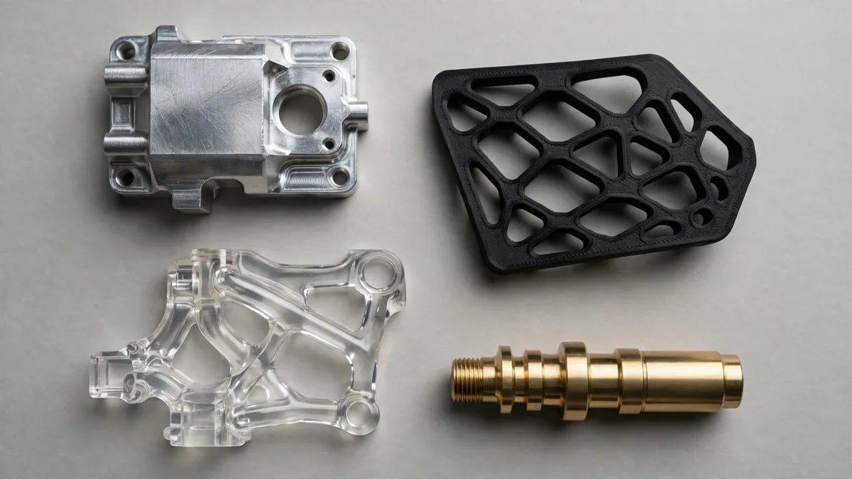
Every 3D printed part starts the same way: a digital model is sliced into thin layers, and a printer builds those layers one on top of another. The choices you make before printing — process, material, and design — decide whether the part comes out strong and clean, or weak and full of supports. This guide walks through the 快速成型 workflow, compares the processes and materials, and covers the rules that prevent common failures.
It is written for engineers and product teams choosing a process for a real part, not for printer buyers. No prices, lead times, or machine specifications are quoted here, because those depend on the part, the quantity, and the printer — the aim is a decision framework you can reuse on any project.
The workflow has five stages, and skipping any of them causes problems later. A clean CAD model, a sensible orientation, and the right slicer settings matter at least as much as the printer itself, because the printer can only reproduce what the file and the settings tell it to.
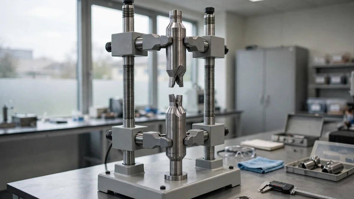
One fact shapes everything else in this guide: a printed part is not equally strong in every direction. The bond between layers is weaker than the material within a layer, so parts are stronger along the printed layers than across them. Orientation is therefore a design decision, not a slicer afterthought.
Seven process families cover nearly all commercial 3D printing, but three of them — FDM, SLA, and SLS — handle most prototyping and low-volume work. The table below compares them on how they work, what they print with, whether they need supports, and where each one earns its place.
| 技术 | How it builds | Typical materials | Supports needed | 最适合 |
|---|---|---|---|---|
| FDM / FFF | Melts plastic filament through a heated nozzle and deposits it along a tool path | PLA, ABS, PETG, Nylon, TPU | Yes, for overhangs and bridges | Affordable functional prototypes, jigs, and fixtures |
| SLA | Cures liquid resin layer by layer with a UV laser | Standard, tough, flexible, castable, and biocompatible resins | Yes, fine supports that leave small marks | Smooth, highly detailed visual and dental models |
| DLP / MSLA | Cures a full resin layer at once with a projector or LCD screen | Photopolymer resins, as for SLA | Yes, as for SLA | Batches of small, detailed resin parts |
| SLS | Fuses nylon powder with a laser; unsintered powder supports the part | Nylon and nylon composites | 没有 | Complex shapes, moving assemblies, and small batches |
| 粘结剂喷射 | Jets liquid binder onto a powder bed, layer by layer | Metal or sand powders, finished by sintering or infiltration | No, the powder bed supports the part | Metal parts and foundry molds at higher volumes |
| Material Jetting | Jets droplets of photopolymer that are cured by UV light | Photopolymers, including multi-material and full-color builds | Yes, gel-like support material | Realistic multi-material prototypes and medical models |
| DED | Melts metal wire or powder with a laser or arc as it is deposited | Metal wire and powder | Depends on geometry | Large metal parts, repairs, and adding features to existing parts |
For resin printing specifically, the choice between laser, projector, and LCD curing changes speed, resolution, and cost in ways that deserve their own comparison — see our SLA 与 DLP 对比指南 for the full breakdown. Metal printing follows the same decision logic with different processes; our metal 3D printing guide covers powder bed fusion, binder jetting, and directed energy deposition in that context.
Material choice is a trade between ease of printing, strength, heat resistance, flexibility, and finish. The table below keeps the comparison qualitative: exact grades and blends vary by supplier, so treat these as starting points for shortlisting, not as datasheet values.
| 材料 | Prints with | 优势 | 请注意 | 典型用途 |
|---|---|---|---|---|
| PLA | FDM | Easy to print, crisp detail, low warping | Brittle; softens in heat | Concept models, form and fit checks |
| ABS | FDM | Tougher than PLA, better heat resistance | Warps without a controlled build environment | Functional prototypes, enclosures, automotive trim |
| PETG | FDM | Good toughness with weather and chemical resistance | Stringing if settings are not tuned | Outdoor parts, brackets, fluid-handling prototypes |
| 尼龙 | FDM, SLS | Strong, wear-resistant, some flex before breaking | Absorbs moisture, which affects printing and parts | Gears, guides, living hinges, end-use parts |
| 热塑性聚氨酯 | FDM | Rubber-like flexibility and impact resistance | Slow to print; flexible filament is harder to feed | Seals, grips, protective covers, footwear parts |
| Photopolymer resin | SLA, DLP, MSLA | Finest detail and smoothest surfaces | Brittle grades exist; washing and curing are mandatory | Dental models, jewelry, miniature and display parts |
| Metal powder | Powder bed fusion, binder jetting, DED | Real metal strength, heat, and durability | Highest cost and post-processing effort | Aerospace brackets, medical implants, tooling inserts |
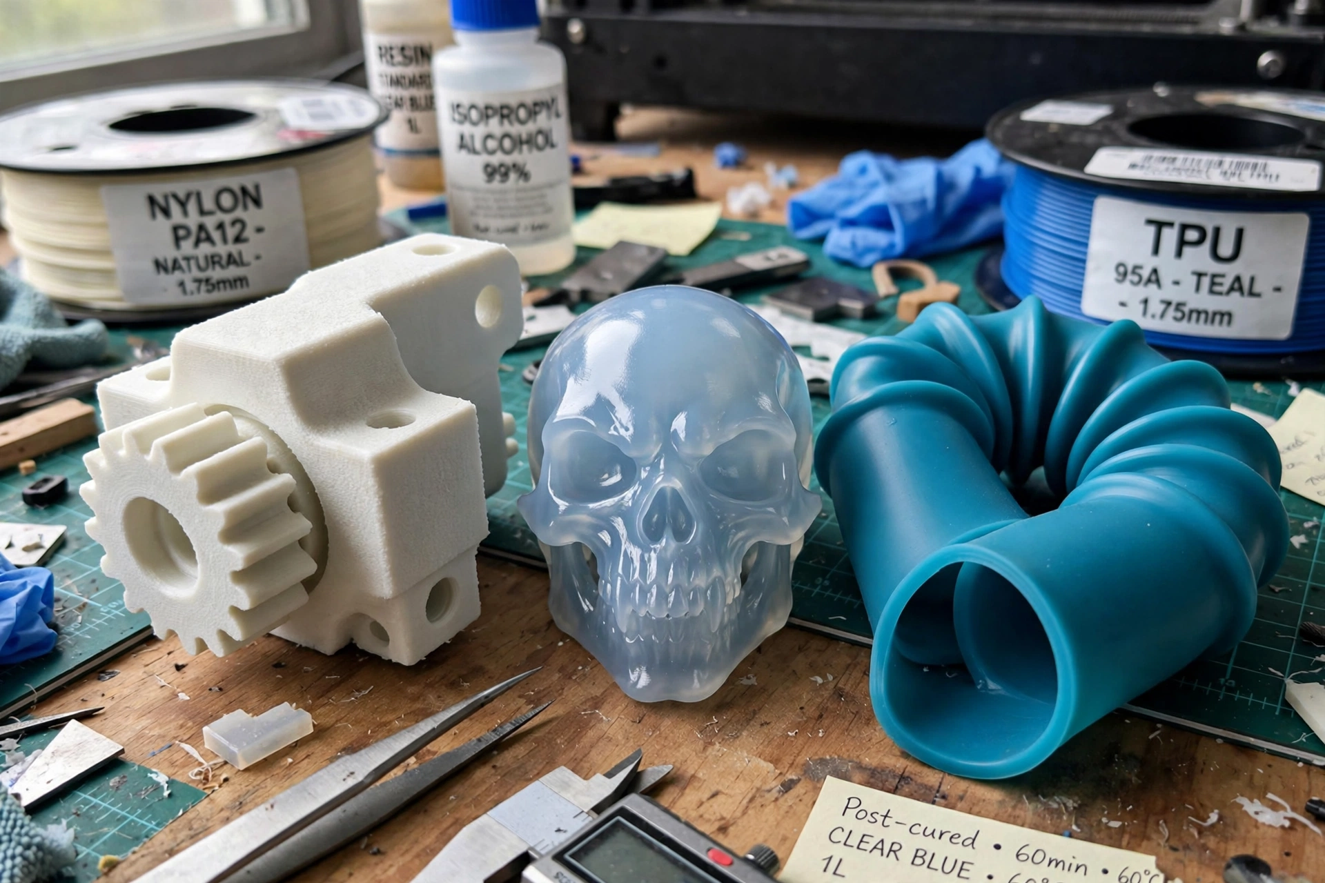
Two selection habits prevent most material mistakes. First, name the part’s worst operating condition — heat, load, impact, chemicals, or outdoor exposure — and eliminate every material that fails it before comparing the rest. Second, check that the material is available on the process you picked, because not every material runs on every printer.
Design for additive manufacturing (DfAM) is mostly about respecting how layers are built. A part designed for machining or molding, then printed unchanged, usually prints badly: thin walls fail, overhangs sag, and supports scar the faces that matter most.
Every process has a smallest feature it can reproduce, set by the nozzle, laser spot, or pixel size and by the material. As a general rule, a single printed wall line cannot be thinner than the nozzle diameter on a filament printer, and functional walls need several lines plus infill behind them. Small holes need care too: on SLS, holes typically need a diameter over 1.5 mm so loose powder can be cleared from them.
Chamfer or fillet sharp internal corners where stress concentrates, and avoid knife-edge features that will break during support removal or handling. If a feature is smaller than the process can resolve, enlarge it, or move that feature to a secondary operation such as drilling or machining after printing.
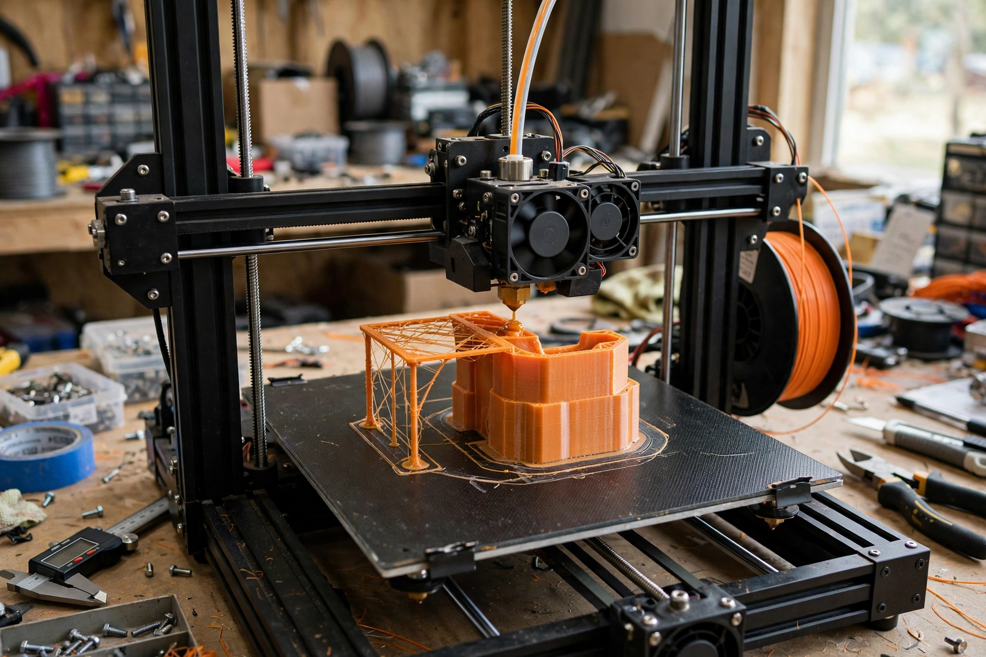
Any layer needs material beneath it, so overhangs and bridges are the classic failure points. As a rule of thumb, surfaces sloping around 45 degrees or less from vertical usually print without supports, while flatter overhangs sag unless supported. Short bridges across a gap can print cleanly; long ones droop, and the safe length depends on the material and the printer.
Supports solve the problem but cost time, material, and surface quality, because the supported face comes out rougher and can be damaged during removal. Reduce them by design: tilt the part, add a chamfer under a ledge, split a difficult part into pieces that each print cleanly, or choose a powder process where the bed itself supports the part.
Orient the part so its layers run perpendicular to the main load, because the layer bond is the weakest direction. This single choice often matters more than picking a stronger material. Laying a part flat usually prints faster with fewer supports, while standing it up can give a smoother visible face but a longer print with more visible layer steps on curved surfaces.
Also think about which faces will carry supports and which faces the user will see. Put supports on hidden or mating faces where their marks do not matter, and keep cosmetic faces support-free wherever the geometry allows.
Layer height is the thickness of each printed layer, and it trades speed against surface quality. Thinner layers give smoother surfaces and finer detail but take longer, because the printer must draw many more layers; thicker layers print faster but leave a more visible stepped texture, especially on curves and shallow slopes.
Infill is the internal structure inside the part’s shell, and it controls weight, strength, and print time together. A sparse infill saves material and time but gives a lighter, weaker part, while a dense infill adds strength at the cost of both. Shells print slowly and supports print very slowly, so surface area and support volume drive print time as much as the part’s overall size does.
3D printing is not a drop-in replacement for machining or molding. Printed parts show layer lines, hold looser tolerances than machined parts unless finished afterwards, and are weaker across layers than along them. Large, solid, blocky parts are often cheaper and faster to machine, because printing fills volume slowly while machining removes it quickly.
Build volume also limits what can print in one piece, and splitting a part introduces joints that must be designed, aligned, and fastened. Where a part needs a precise bore, a smooth sealing face, or a tight thread, plan a finishing step — drilling, reaming, tapping, or machining — rather than expecting the printed surface to meet the requirement alone.
The technology earns its place where geometry is complex, quantities are low, or speed of iteration matters more than unit cost. Typical wins include functional prototypes that must be tested, not just looked at; jigs, fixtures, and factory aids made for one line or one job; patient-specific medical models and guides; lightweight brackets and ducts with internal channels; and short runs of parts that would need expensive tooling any other way.
Printed-part cost comes from four buckets: material used, machine time, labor for setup and finishing, and any post-processing the part needs. Material volume is set by the part’s size and its shell and infill choices; machine time is driven by surface area, support volume, and layer count rather than by part weight alone; and finishing labor can exceed printing time on parts that need sanding, curing, or coating.
Three design moves cut cost without weakening the part. Hollow out bulky sections with a sensible infill instead of printing them solid, consolidate assemblies into single printed parts where the geometry allows, and batch small parts together on one build so setup and post-processing are shared across the whole plate.
Work through the part’s requirements in this order: function first, then size and quantity, then finish, then cost. A part that must survive heat or load eliminates whole process families at once, and that shortlist is more useful than any ranking of printers. When two processes both fit, the one with simpler post-processing and fewer supports usually wins on total time and cost.
If the answers point to a resin process, compare curing methods before committing, and if they point to a service bureau rather than an owned printer, our 3D打印服务 page covers project-based work. For a deeper look at how prototyping fits product development, start with the rapid prototyping guide linked at the top of this article.
Start with what the part must do, not with the printer. A visual prototype needs surface finish and detail, so a resin process usually wins. A functional part needs strength, heat resistance, or flexibility, which points to a filament or powder process. Then check size, quantity, and budget. If two processes both fit, pick the one with the simpler post-processing.
Match the material to the part’s job. PLA is easy to print and good for form and fit checks, but it is brittle and softens in heat. ABS handles higher temperatures and tougher handling, while PETG adds weather and chemical resistance. Nylon suits parts that must flex without breaking, and TPU is the pick for rubber-like flexibility.
Printed parts are strongest along the printed layers and weakest between them, because the bond between layers is the part’s weak point. Orienting the part so the layers run perpendicular to the main load makes it far harder to break. Orientation also controls supports, surface quality, and print time.
Keep overhangs gentle: as a rule of thumb, surfaces sloping around 45 degrees or less from vertical print without supports, while flatter overhangs sag. Add chamfers instead of sharp horizontal ledges, split the part so each piece prints in a friendly orientation, and bridge only short gaps. Where supports are unavoidable, place them on faces that will not be seen.
FDM melts plastic filament through a heated nozzle, layer by layer; it is the most affordable route for functional prototypes. SLA cures liquid resin with a UV laser for very smooth, detailed parts. SLS fuses nylon powder with a laser and needs no supports, because unsintered powder holds the part up.
Almost every printed part needs support removal first. FDM parts are then sanded or smoothed, and resin parts must be washed to remove uncured resin and cured again under UV light. SLS parts are cleaned of loose powder. Painting, coating, or machining can follow when the part needs a specific finish, tighter tolerance, or a functional surface.
Reviewed by Leon Xu, Engineer, Tuowei Precision. Last updated: November 2026. Figures quoted here come from the sources above; where a value depends on the printer, material, or settings, the guide says so rather than quoting a single number.