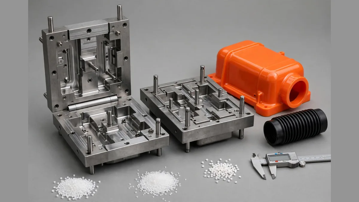
Injection molding design guidelines exist for one reason: to keep the plastic flowing where it should, cooling at the rate it should and releasing from the mold without sticking, warping or showing defects. Every rule traces back to how molten polymer behaves under pressure and temperature, and once you understand that link, the guidelines stop feeling arbitrary.
Short answer: Keep walls uniform, add draft to every surface that parallels the direction of mold opening, place gates where flow reaches every corner before the melt freezes, and size ribs to reinforce without causing sink marks on the opposite face. The tables below give the numbers for common resins.
Wall thickness injection molding problems cause more part rejections than any other design error. Walls that are too thick sink, warp and extend cycle time. Walls that are too thin cause short shots and high injection pressure. Walls that vary in thickness cool at different rates, which pulls the part out of shape.
The goal is uniform wall thickness throughout the part. Where thickness must change, transition gradually over a distance of at least 3 times the thickness difference to avoid stress concentration and flow hesitation.
| 树脂 | Recommended wall (mm) | Max practical wall (mm) |
|---|---|---|
| ABS | 1.5 to 3.0 | 4.5 |
| 聚碳酸酯(PC) | 1.5 to 3.5 | 5.0 |
| 聚丙烯(PP) | 0.8 to 2.5 | 4.0 |
| Polyethylene (PE) | 0.8 to 3.0 | 4.0 |
| 尼龙(PA6、PA66) | 1.0 to 3.0 | 4.5 |
| POM(Delrin) | 1.0 to 3.0 | 4.5 |
| TPE / TPU | 1.0 to 3.0 | 5.0 |
| PMMA (acrylic) | 1.5 to 4.0 | 6.0 |
| PC/ABS blend | 1.5 to 3.5 | 5.0 |
| Glass-filled nylon | 1.5 to 4.0 | 6.0 |
These numbers assume a part with moderate flow length. Very large parts or long, thin parts may need thicker walls to fill completely. Very small parts or parts with short flow lengths can use thinner walls.
Draft is the slight taper applied to surfaces that run parallel to the direction the mold opens. Without it, the part grips the core or cavity as it cools and shrinks, making ejection difficult and scratching the part surface on the way out.
Minimum draft angles by surface type:
| Surface type | Minimum draft | Preferred draft |
|---|---|---|
| Smooth, untextured surface | 0.5 degrees | 1.0 to 1.5 degrees |
| Light texture (SPI B or C) | 1.0 degrees + 1 degree per 0.025 mm texture depth | 2 to 3 degrees |
| Heavy texture (VDI 30+) | 3 degrees or more | 5 degrees |
| Ribs and bosses | 0.5 degrees minimum | 1.0 degree |
| Deep features (>50 mm) | 1.0 degree minimum | 1.5 to 2.0 degrees |
| Shutoff surfaces | 3 degrees minimum | 5 degrees |
The rule that catches most designers: textured surfaces need more draft than smooth ones. The texture creates undercuts at a microscopic level, and without enough draft the texture scrapes during ejection. The SPI (Society of the Plastics Industry) and VDI 3400 standards define texture grades and their corresponding draft requirements.
The gate is where molten plastic enters the cavity. Its location, size and type affect fill pattern, weld-line position, cosmetic appearance and packing pressure. Getting the gate wrong shows up as short shots, burn marks, visible gate vestiges, or weld lines on a cosmetic face.
| Gate type | Gate size | 最适合 | Vestige | Auto-trim? | Cost impact |
|---|---|---|---|---|---|
| Edge gate | 1 to 3 mm wide | Flat parts, simple fills | Visible tab on edge | No, manual trim | 低 |
| Sub-gate (tunnel) | 0.5 to 1.5 mm | Parts needing auto-degating | Small pip | Yes, shears on eject | 中型 |
| Pin-point gate | 0.5 to 1.0 mm | Multi-cavity, hot runner | Tiny dot | 是 | Higher (hot runner) |
| Fan gate | Wide, thin | Large flat parts | Wide mark on edge | 没有 | 低 |
| Cashew gate | Curved tunnel | Underside gating, hidden vestige | Hidden | 是 | 中型 |
| Valve gate | Controlled by pin | No vestige, cosmetic parts | Flush or none | 是 | Highest (hot runner) |
Gate placement rules:
Gate into the thickest section so the thickest area packs last, reducing sink.
Position weld lines away from cosmetic surfaces and high-stress areas.
Avoid gating directly opposite a core pin, which deflects the pin and causes wall variation.
For long parts, consider multiple gates to reduce flow length and injection pressure.
Runner systems (cold runner vs. hot runner) affect material waste, cycle time and gate vestige. Cold runners are cheaper to build and maintain but waste material in the runner itself. Hot runners keep the runner molten, eliminating runner scrap, and are standard for high-volume production and multi-cavity molds.
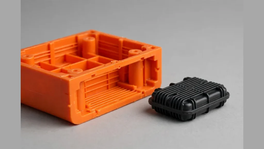
Ribs add stiffness without adding wall thickness. Bosses provide mounting points for screws or inserts. Both concentrate material in one spot, so if they are too thick relative to the wall they cause sink marks on the opposite face.
Rib proportions:
Rib base thickness: 50 to 70% of the adjacent wall thickness. For a 2 mm wall, the rib base should be 1.0 to 1.4 mm.
Rib height: up to 3 times the wall thickness. Beyond that, the rib is difficult to fill and prone to warping.
Rib draft: 0.5 to 1.0 degree per side.
Rib spacing: at least 2 times the wall thickness between parallel ribs.
Rib base radius: 0.25 to 0.5 times the wall thickness. Too large a radius concentrates material and causes sink; too small creates stress.
Boss proportions:
Boss outside diameter: 2 to 2.5 times the screw or insert diameter.
Boss wall thickness: 60% of the nominal wall, with supporting ribs if the boss is tall.
Boss height: ideally no more than 2.5 times the outside diameter.
Standalone bosses should be connected to a wall or corner with supporting ribs, not left isolated.
The parting line is where the two mold halves meet. Its location affects the part’s cosmetic appearance, dimensional accuracy and the complexity of the mold. Parting line placement is a DFM injection molding decision that should be made early, not left to the tool shop.
Parting line guidelines:
Place the parting line on a flat surface or along a sharp edge where a small witness line is least visible.
Avoid parting lines across curved or textured cosmetic surfaces, where mismatch shows clearly.
Keep the parting line at the widest cross-section of the part so both halves can release.
Ejection: Ejector pins leave small witness marks where they push the part off the core. Place ejector pins on non-cosmetic faces, behind ribs, on structural edges or inside bosses. Ejector pin diameter should be as large as possible to spread force and prevent punch-through on thin walls. For deep parts, sleeve ejectors or stripper plates distribute force more evenly than pins.
Undercuts: Any feature that prevents the part from pulling straight out of the mold in the direction of opening is an undercut. Undercuts require side actions (slides or lifters), collapsible cores or pick-outs, all of which add mold cost and complexity. If possible, redesign undercuts into through-holes, snap-fit geometry with enough flex for release, or separate components assembled after molding.
Injection molded parts cannot be held to the same tolerances as CNC machined parts. Plastic shrinks as it cools (0.3 to 2.5% depending on resin), and that shrinkage varies with gate location, wall thickness, cooling rate and packing pressure. Realistic tolerance expectations avoid expensive mold rework.
| Resin type | Mold shrinkage (%) | 标准公差 | Tight tolerance |
|---|---|---|---|
| ABS | 0.4 to 0.7 | ±0.1 毫米 | ±0.05 毫米 |
| 个人电脑 | 0.5 to 0.7 | ±0.1 毫米 | ±0.05 毫米 |
| 聚丙烯 | 1.0 to 2.5 | ±0.2 毫米 | ±0.1 毫米 |
| PE | 1.5 to 3.0 | ±0.3 毫米 | ±0.15 毫米 |
| Nylon (unfilled) | 0.8 to 1.5 | ±0.15 毫米 | ±0.08 mm |
| Nylon (glass-filled) | 0.3 to 0.6 | ±0.1 毫米 | ±0.05 毫米 |
| POM | 1.5 to 2.5 | ±0.15 毫米 | ±0.08 mm |
| PMMA | 0.4 to 0.7 | ±0.1 毫米 | ±0.05 毫米 |
High-shrinkage resins like PP and PE are inherently less dimensionally stable than low-shrinkage materials like glass-filled nylon. If the design requires tight tolerances in a high-shrinkage resin, consider switching to a glass-filled or mineral-filled grade, which reduces and stabilizes shrinkage.
For features that must align with other parts, GD&T (geometric dimensioning and tolerancing) per ASME Y14.5 specifies position, flatness and profile more precisely than a bilateral tolerance on each dimension. GD&T also communicates which features are datums, so the mold maker and the inspection team reference the same surfaces.
Surface texture on injection molded parts is applied to the mold cavity, so every part carries a consistent finish at no per-part cost. Two standards dominate:
SPI (Society of the Plastics Industry) defines grades A-1 through D-3, from mirror polish to coarse sandblast. SPI A grades require hardened mold steel and diamond polishing. SPI B and C grades cover most consumer products. SPI D grades are matte or textured finishes used to hide flow marks.
VDI 3400 uses a numeric scale from 0 (mirror) to 45 (very coarse). VDI textures are achieved by EDM (electrical discharge machining) of the mold surface. VDI 12 to VDI 27 are common for consumer electronics enclosures and automotive interior parts.
Textured surfaces need extra draft (see the draft table above). A common mistake is specifying a VDI 30 texture and 1 degree of draft. The ejection force will scrape the texture, leaving marks or sticking the part. For heavy textures, 3 to 5 degrees of draft is realistic.
As plastic fills the cavity, air must escape. Inadequate venting traps air, which compresses and heats until it burns the plastic (diesel effect) or prevents the cavity from filling completely. Burn marks at the last-to-fill areas of a part are almost always a venting problem.
Vent dimensions by resin:
| Resin type | Vent depth (mm) | Vent width (mm) |
|---|---|---|
| ABS、PC、PC/ABS | 0.025 to 0.05 | 5 to 10 |
| PP, PE | 0.025 to 0.038 | 5 to 10 |
| Nylon (unfilled) | 0.013 to 0.025 | 5 to 8 |
| Nylon (glass-filled) | 0.025 to 0.05 | 5 to 10 |
| POM | 0.013 to 0.025 | 5 to 8 |
| TPE / TPU | 0.013 to 0.025 | 5 to 8 |
Vents should be placed at the last points to fill, along the parting line and around core pins. The vent channel leads from the vent land to the mold edge. Vent depth must be shallow enough to let air pass but prevent plastic from flashing. If venting at the parting line is not enough, sintered steel vent inserts or vacuum-assisted venting may be needed.
Injection molding design guidelines are most useful before the mold is cut, not after. A thorough DFM injection molding review catches wall thickness problems, missing draft, gate placement issues and tolerance conflicts while changes cost nothing.
在 拓维精密, our injection molding services include a DFM review before mold cutting begins. The review flags sink-risk areas, recommends gate type and location, confirms draft on every surface and checks tolerance feasibility against the chosen resin.
For projects that start with a CNC machined prototype (数控加工服务) before moving to injection molding, the prototype test results inform the mold design. Features that need tighter tolerances in the molded part are identified during prototype testing rather than discovered at first article inspection.
If your project involves 精密机械加工 of mold inserts or 航空航天零部件 that require documented traceability, those requirements should be stated at the DFM stage so the mold is designed to produce parts that pass the required inspection.
ABS wall thickness should be 1.5 to 3.0 mm for most parts, with 4.5 mm as a practical maximum. Keep walls uniform throughout the part. Where thickness must change, transition gradually over at least 3 times the difference to avoid sink and stress marks.
Start with the minimum draft for the texture depth. For light SPI B or C textures, 1 to 2 degrees per side is usually sufficient. For heavier textures like VDI 30 or above, 3 to 5 degrees is needed. The rule of thumb is 1 degree of additional draft per 0.025 mm of texture depth beyond a smooth surface.
Sink marks appear when thick sections cool and shrink more than surrounding thin sections, pulling the surface inward. The most common causes are ribs that are too thick relative to the wall, bosses without reduced wall thickness, and abrupt wall thickness changes. Keep rib base thickness at 50 to 70% of the adjacent wall.
Polypropylene has high mold shrinkage (1.0 to 2.5%), so standard tolerances are ±0.2 mm and tight tolerances reach ±0.1 mm. For tighter requirements, consider a glass-filled or mineral-filled PP grade, which reduces shrinkage and improves dimensional stability.
Cold runners are cheaper to build and maintain, suitable for low to medium volumes and simple parts. Hot runners eliminate runner scrap, reduce cycle time and improve gate control, but add $5,000 to $15,000 or more to the mold cost. Hot runners pay for themselves at high volumes or when material cost is high.